PART 3: CX-Server Runtime
CHAPTER 3 – Communications
OMRON
CX-Server Runtime_Page 16
Revision 2.0
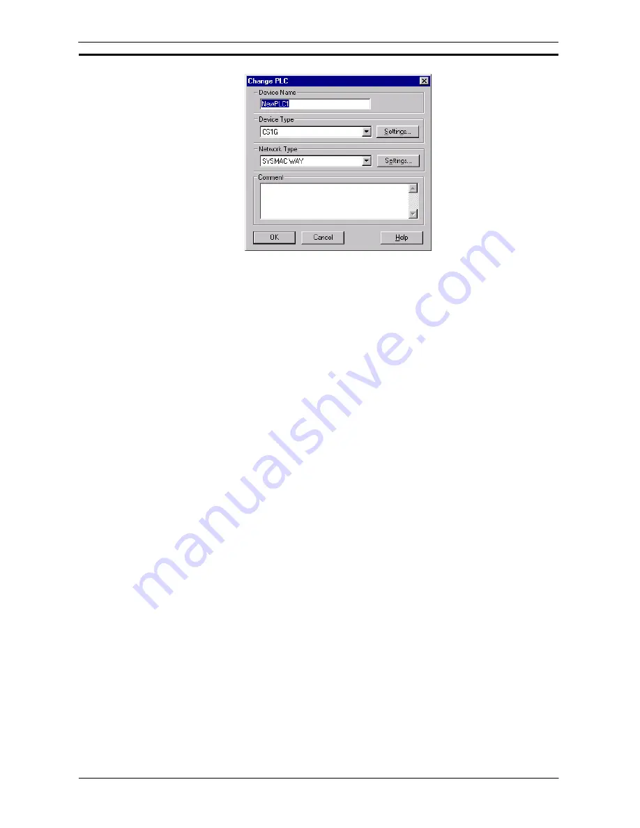
Use the following procedure to change the PLC settings:
1, 2, 3…
1. Enter a name in the
Device Name
field. A device name must consist of no more than 32
characters and must be unique.
2. Select the device type of the PLC in the
Device Type
field. If the device requirement does
not appear in the list then CX-Server does not support it.
3. Further configure the device type (e.g. CPU number) by selecting the Device Type
Settings
pushbutton. Refer to
Chapter 3 - Device Type Settings
for further details.
4.
Select the network type of the PLC in the
Network Type
field. This list may include other
PLCs in the CX-Server project that can be used as gateway devices, depending upon the
device type chosen. A full list of connection types are provided below.
5.
Further configure the network settings (e.g. node number) if applicable by selecting the
Network Type
Settings
pushbutton. Refer to
Chapter 3 - Network Communications (End
Connection)
for further details.
6.
Optionally, enter a comment relating to this unique PLC in the
Comment
field.
7.
Select the
OK
pushbutton to save the new PLC or the
Cancel
pushbutton to abort the
operation.
Note:
The Device Name must
not
contain any of the following characters: / \ : ; , ? * & ! . “
but may include spaces and international characters. The Device Name is case
sensitive, i.e. if a name is entered in upper case which already exists in lower case, a
new PLC is created. The contents of the Network field depend upon the device type
settings of the new PLC. The Device Type
Settings
pushbutton is disabled for the
following devices: C20, FinsGateway, Memory Card Writer and Programmable Read
Only Memory (PROM) Writer, since these devices do not have options. Any PLCs
which have been set up and can act as a gateway device appear in the
Device Type
field.
A full list of connection methods is as follows:
♦
SYSMAC WAY
.
♦
Toolbus
. Toolbus on the CS/CJ/CP-series PLCs allows CX-Server auto-baud rate detection up to 115,200
bps. Toolbus on the CS/CJ/CP-series PLCs supports full
n
clients and
n
destinations.
♦
When the PLC model is set as a CP1H CPU Unit equipped with a USB port, a computer’s USB port can be
connected directly to the PLC’s built-in USB port with a standard USB cable.
♦
With a CP1E CPU Unit, the Toolbus connection cannot be used for serial communications. Connect via
USB or SYSMAC WAY.
♦
Modem via SYSMAC WAY
. Modem is supported through SYSMAC WAY communications via Windows
TAPI configuration.
♦
Modem via Toolbus
. Modem is supported through Toolbus communications via Windows TAPI
configuration.
♦
Ethernet via TCP/IP
. Ethernet is only supported for CS/CJ/CP-series PLCs, CV-series PLCs and
C200HE/G/X/E-Z/G-Z/X-Z series PLCs. All Ethernet connections now also support full
n
clients and
n
destinations via CX-Server Ethernet driver. CX-Server also utilises FinsGateway Version 3 Ethernet driver
if the required PLC connection UDP port is locked open by FinsGateway active running services.
Summary of Contents for CX-PROGRAMMER V9
Page 1: ...Cat No W446 E1 12 CX Programmer Ver 9 CXONE AL_C V4 AL_D V4 SYSMAC OPERATION MANUAL...
Page 2: ......
Page 3: ...SYSMAC CX Programmer Ver 9 CXONE AL C V4 AL D V4 Operation Manual Revised July 2010...
Page 4: ......
Page 6: ......
Page 32: ......
Page 33: ...PART 1 CX Programmer...
Page 34: ......
Page 91: ......
Page 111: ......
Page 191: ...PART 1 CX Programmer CHAPTER 4 Reference OMRON CX Programmer _Page 108...
Page 217: ......
Page 233: ......
Page 234: ...PART 2 CX Server PLC Tools...
Page 235: ......
Page 243: ......
Page 249: ......
Page 261: ...PART 2 CX Server PLC Tools CHAPTER 2 PLC Memory Component OMRON CX Server PLC Tools_Page 18...
Page 280: ......
Page 333: ......
Page 377: ......
Page 409: ......
Page 430: ......
Page 431: ...PART 3 CX Server Runtime...
Page 432: ......
Page 476: ......
Page 482: ......
Page 498: ......
Page 524: ......
Page 534: ......
Page 535: ......
Page 536: ......


