


FlexCAN Module
MCF5253 Reference Manual, Rev. 1
Freescale Semiconductor
25-5
ignores the bit sent during the ACK slot in the CAN frame acknowledge field to ensure proper reception
of its own message. Both transmit and receive interrupts are generated.
25.3.2.5
Listen-only Mode
In listen-only mode, transmission is disabled, all error counters are frozen and the module operates in a
CAN error passive mode. Only messages acknowledged by another CAN station will be received. If
FlexCAN detects a message that has not been acknowledged, it will flag a BIT0 error (without changing
the REC), as if it was trying to acknowledge the message. Because the module does not influence the CAN
bus in this mode, the device is capable of functioning like a monitor or for automatic bit-rate detection.
25.4
External Signal Description
Each FlexCAN module has two I/O signals connected to the external MPU pins: CAN0TX, CAN0RX,
CAN1TX, and CAN1RX. CAN
n
TX transmits serial data to the CAN bus transceiver, while CAN
n
RX
receives serial data from the CAN bus transceiver.
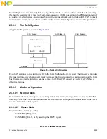
25.5
Memory Map and Register Definitions
The FlexCAN module address space is split into 128 bytes starting at the base address, and then an extra
512 bytes starting at the base a128. The upper 512 are fully used for the message buffer structures,
as described in
Section 25.5.9, “Message Buffer Structure.”
Out of the lower 128 bytes, only part is
occupied by various registers.
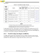
Table 25-1. FlexCAN Memory Map
MBAR2
Offset
Register
Width
(Bits)
Affected
by Hard
Reset
Affected
by Soft
Reset
Access
Reset Value
Section/Page
FlexCAN0
FlexCAN1
Supervisor-only Access Registers
0x1000
0x2000
FlexCAN Module Configuration
Register (CANMCRn)
32
Y
Y
R/W
0xD890_000F
Supervisor/User Access Registers
0x1004
0x2004
FlexCAN Control Register
(CANCTRLn)
32
Y
N
R/W
0x0000_0000
0x1008
0x2008
Free Running Timer (TIMERn)
32
Y
Y
R/W
0x0000_0000
0x1010
0x2010
Rx Global Mask (RXGMASKn)
32
Y
N
R/W
0x1FFF_FFFF
0x1014
0x2014
Rx Buffer 14 Mask (RX14MASkn)
32
Y
N
R/W
0x1FFF_FFFF
0x1018
0x2018
Rx Buffer 15 Mask (RX15MASKn)
32
Y
N
R/W
0x1FFF_FFFF
Summary of Contents for MCF5253
Page 1: ...Document Number MCF5253RM Rev 1 08 2008 MCF5253 Reference Manual...
Page 26: ...MCF5253 Reference Manual Rev 1 xxvi Freescale Semiconductor...
Page 32: ...MCF5253 Reference Manual Rev 1 xxxii Freescale Semiconductor...
Page 46: ...MCF5253 Introduction MCF5253 Reference Manual Rev 1 1 14 Freescale Semiconductor...
Page 62: ...Signal Description MCF5253 Reference Manual Rev 1 2 16 Freescale Semiconductor...
Page 98: ...Instruction Cache MCF5253 Reference Manual Rev 1 5 10 Freescale Semiconductor...
Page 104: ...Static RAM SRAM MCF5253 Reference Manual Rev 1 6 6 Freescale Semiconductor...
Page 128: ...Synchronous DRAM Controller Module MCF5253 Reference Manual Rev 1 7 24 Freescale Semiconductor...
Page 144: ...Bus Operation MCF5253 Reference Manual Rev 1 8 16 Freescale Semiconductor...
Page 176: ...System Integration Module SIM MCF5253 Reference Manual Rev 1 9 32 Freescale Semiconductor...
Page 198: ...Analog to Digital Converter ADC MCF5253 Reference Manual Rev 1 12 6 Freescale Semiconductor...
Page 246: ...DMA Controller MCF5253 Reference Manual Rev 1 14 18 Freescale Semiconductor...
Page 282: ...UART Modules MCF5253 Reference Manual Rev 1 15 36 Freescale Semiconductor...
Page 344: ...Audio Interface Module AIM MCF5253 Reference Manual Rev 1 17 46 Freescale Semiconductor...
Page 362: ...I2 C Modules MCF5253 Reference Manual Rev 1 18 18 Freescale Semiconductor...
Page 370: ...Boot ROM MCF5253 Reference Manual Rev 1 19 8 Freescale Semiconductor...