


Audio Interface Module (AIM)
MCF5253 Reference Manual, Rev. 1
Freescale Semiconductor
17-37
17.7.7.4
Audio Interrupt Routines and Timing
Usually, the processor will run an audio interrupt routine. Every time the audio interrupt routine runs, it
will process 2, 3, or 4 audio samples, and send this many samples to one or more PDOR output registers.
Also, the audio interrupt routine will read one or more PDIR registers until empty.
In the audio interrupt routine, typically at the beginning, the PDIR registers are read until empty, while the
PDOR registers are written at the end of the routine when all calculations are completed. Due to this
calculation latency, there is a delay between entering the audio interrupt routine and the filling of the
transmit FIFOs.
Due to this delay, it is difficult to “fire” the audio interrupt routine on a transmit FIFO empty interrupt.
Because of the extra delay before the data is written, the transmit
FIFO
will underrun before any data is
written.
To make it easy for the programmer, the audioTick interrupt was added. To start the audio interrupt routine,
use the following sequence:
1. Reset the transmit FIFOs
2. Program the transmit FIFOs to the correct source, then release the reset on transmit FIFOs
3. Reset the PDIR FIFOs
4. Load audio interrupt routine in on-chip SRAM
5. Release reset for the PDIR FIFOs and enable audioTick interrupt
The transmit FIFOs have a special feature. After the software releases the reset to them, they will stay in
reset until the audio Interrupt Routine writes data to them for the first time. So, during Step 2 of above
mentioned start-up procedure, all transmit FIFO’s are set in reset, with one sample remaining. They will
stay in this state, until the audio Interrupt Routine writes data to them. At this point in time, they are then
filled up with an extra 2, 3, or 4 samples to a total of 3, 4, or 5 samples. Also, the first data write to the
FIFOs releases the reset, and starts transmission of the FIFO data on the corresponding transmit output.
(IIS1, IIS2 or IEC958). The next time that data is written to the FIFO’s in the audioTick interrupt routine,
2,3, or 4 samples have been transmitted and the FIFO is ready to accept new data.
To work properly, the jitter from one audioTick write point to the next is important. Jitter should be lower
than 1 sample period if data is written in groups of 2 or 3 samples to the transmit FIFOs, and lower than
1/2 sample period if data is written in groups of 4 samples to the transmit FIFOs.
The receive FIFO’s (PDIR’s) don’t have an auto-reset-de-assert mechanism, and should be released out of
reset just before enabling audioTick interrupt.
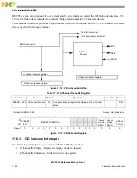
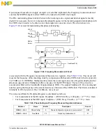
shows the timing (relative to the Word Clock) of the Empty, Under-run, and Audio Tick
interrupts. Each FIFO holds up to six audio samples (left and right).
The Empty Interrupt occurs when there is still one right sample left to be transmitted, thus giving the
system one audio sample length to fill the FIFO back-up. The Underrun Interrupt occurs when there are
no samples left to be transmitted. While this is a situation that should be taken seriously, it will rarely occur,
if at all. However, should this happen, the system will continue to repeat the last sample until the FIFO
buffer has new data.
Summary of Contents for MCF5253
Page 1: ...Document Number MCF5253RM Rev 1 08 2008 MCF5253 Reference Manual...
Page 26: ...MCF5253 Reference Manual Rev 1 xxvi Freescale Semiconductor...
Page 32: ...MCF5253 Reference Manual Rev 1 xxxii Freescale Semiconductor...
Page 46: ...MCF5253 Introduction MCF5253 Reference Manual Rev 1 1 14 Freescale Semiconductor...
Page 62: ...Signal Description MCF5253 Reference Manual Rev 1 2 16 Freescale Semiconductor...
Page 98: ...Instruction Cache MCF5253 Reference Manual Rev 1 5 10 Freescale Semiconductor...
Page 104: ...Static RAM SRAM MCF5253 Reference Manual Rev 1 6 6 Freescale Semiconductor...
Page 128: ...Synchronous DRAM Controller Module MCF5253 Reference Manual Rev 1 7 24 Freescale Semiconductor...
Page 144: ...Bus Operation MCF5253 Reference Manual Rev 1 8 16 Freescale Semiconductor...
Page 176: ...System Integration Module SIM MCF5253 Reference Manual Rev 1 9 32 Freescale Semiconductor...
Page 198: ...Analog to Digital Converter ADC MCF5253 Reference Manual Rev 1 12 6 Freescale Semiconductor...
Page 246: ...DMA Controller MCF5253 Reference Manual Rev 1 14 18 Freescale Semiconductor...
Page 282: ...UART Modules MCF5253 Reference Manual Rev 1 15 36 Freescale Semiconductor...
Page 344: ...Audio Interface Module AIM MCF5253 Reference Manual Rev 1 17 46 Freescale Semiconductor...
Page 362: ...I2 C Modules MCF5253 Reference Manual Rev 1 18 18 Freescale Semiconductor...
Page 370: ...Boot ROM MCF5253 Reference Manual Rev 1 19 8 Freescale Semiconductor...


