


Universal Serial Bus Interface
MCF5253 Reference Manual, Rev. 1
24-124
Freescale Semiconductor
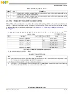
24.10.1.2 Transfer Overlay
The seven DWords in the overlay area represent a transaction working space for the device controller. The
general operational model is that the device controller can detect whether the overlay area contains a
description of an active transfer. If it does not contain an active transfer, then it will not read the associated
endpoint.
After an endpoint is readied, the dTD will be copied into this queue head overlay area by the device
controller. Until a transfer is expired, the software must not write the queue head overlay area or the
associated transfer descriptor. When the transfer is complete, the device controller will write the results
back to the original transfer descriptor and advance the queue.
See dTD for a description of the overlay fields.
24.10.1.3 Current dTD Pointer
The current dTD pointer is used by the device controller to locate the transfer in progress. This word is for
USB_DR (hardware) use only and should not be modified by DCD software.
24.10.1.4 Set-Up Buffer
The set-up buffer is dedicated storage for the 8-byte data that follows a set-up PID.
NOTE
Each endpoint has a TX and an RX dQH associated with it, and only the RX
queue head is used for receiving setup data packets.
29
zlt
Zero length termination select. This bit is used to indicate when a zero length packet is used to terminate
transfers where to total transfer length is a multiple. This bit is not relevant for Isochronous transfers.
0 Enable zero length packet to terminate transfers equal to a multiple of the Maximum Packet Length.
(default).
1 Disable the zero length packet on transfers that are equal in length to a multiple Maximum Packet
Length.
28–27
–
Reserved. These bit reserved for future use and should be cleared.
26–16
Maximum
Packet
Length
Maximum packet length. This directly corresponds to the maximum packet size of the associated endpoint
(wMaxPacketSize). The maximum value this field may contain is 0x400 (1024).
15
ios
Interrupt on setup (IOS). This bit is used on control type endpoints to indicate if USBINT is set in response
to a setup being received.
14–0
Reserved. Bits reserved for future use and should be cleared.
Table 24-75. Current dTD Pointer
Bit
Description
31–5
Current dtd. This field is a pointer to the dTD that is represented in the transfer overlay area. This field will be
modified by the Device Controller to next dTD pointer during endpoint priming or queue advance.
4–0
Reserved. Bit reserved for future use and should be cleared.
Table 24-74. Endpoint Capabilities/Characteristics (continued)
Bit
Name
Description
Summary of Contents for MCF5253
Page 1: ...Document Number MCF5253RM Rev 1 08 2008 MCF5253 Reference Manual...
Page 26: ...MCF5253 Reference Manual Rev 1 xxvi Freescale Semiconductor...
Page 32: ...MCF5253 Reference Manual Rev 1 xxxii Freescale Semiconductor...
Page 46: ...MCF5253 Introduction MCF5253 Reference Manual Rev 1 1 14 Freescale Semiconductor...
Page 62: ...Signal Description MCF5253 Reference Manual Rev 1 2 16 Freescale Semiconductor...
Page 98: ...Instruction Cache MCF5253 Reference Manual Rev 1 5 10 Freescale Semiconductor...
Page 104: ...Static RAM SRAM MCF5253 Reference Manual Rev 1 6 6 Freescale Semiconductor...
Page 128: ...Synchronous DRAM Controller Module MCF5253 Reference Manual Rev 1 7 24 Freescale Semiconductor...
Page 144: ...Bus Operation MCF5253 Reference Manual Rev 1 8 16 Freescale Semiconductor...
Page 176: ...System Integration Module SIM MCF5253 Reference Manual Rev 1 9 32 Freescale Semiconductor...
Page 198: ...Analog to Digital Converter ADC MCF5253 Reference Manual Rev 1 12 6 Freescale Semiconductor...
Page 246: ...DMA Controller MCF5253 Reference Manual Rev 1 14 18 Freescale Semiconductor...
Page 282: ...UART Modules MCF5253 Reference Manual Rev 1 15 36 Freescale Semiconductor...
Page 344: ...Audio Interface Module AIM MCF5253 Reference Manual Rev 1 17 46 Freescale Semiconductor...
Page 362: ...I2 C Modules MCF5253 Reference Manual Rev 1 18 18 Freescale Semiconductor...
Page 370: ...Boot ROM MCF5253 Reference Manual Rev 1 19 8 Freescale Semiconductor...


