


Universal Serial Bus Interface
MCF5253 Reference Manual, Rev. 1
Freescale Semiconductor
24-145
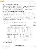
Case 2: Link list is not empty
1. Add dTD to end of linked list.
2. Read correct prime bit in ENDPTPRIME
—
if 1 DONE.
3. Set ATDTW bit in USBCMD register to 1.
4. Read correct status bit in ENDPTSTATUS. (store in tmp. variable for later)
5. Read ATDTW bit in USBCMD register.
If 0 goto 3.
If 1 continue to 6.
6. Write ATDTW bit in USBCMD register to '0'.
7. If status bit read in (3) is '1' DONE.
8. If status bit read in (3) is '0' then Goto Case 1: Step 1.
24.11.5.4 Transfer Completion
After a dTD has been initialized and the associated endpoint primed the device controller will execute the
transfer upon the host-initiated request. The DCD will be notified with a USB interrupt if the Interrupt On
Complete bit was set or alternately, the DCD can poll the endpoint complete register to find when the dTD
had been executed. After a dTD has been executed, DCD can check the status bits to determine success or
failure.
CAUTION
Multiple dTD can be completed in a single endpoint complete notification.
After clearing the notification, DCD must search the dTD linked list and
retire all dTDs that have finished (Active bit cleared).
By reading the status fields of the completed dTDs, the DCD can determine if the transfers completed
successfully. Success is determined with the following combination of status bits:
•
Active = 0
•
Halted = 0
•
Transaction Error = 0
•
Data Buffer Error = 0
Should any combination other than the one shown above exist, the DCD must take proper action. Transfer
failure mechanisms are indicated in the Device Error Matrix.
In addition to checking the status bit the DCD must read the Transfer Bytes field to determine the actual
bytes transferred. When a transfer is complete, the Total Bytes transferred is by decremented by the actual
bytes transferred. For Transmit packets, a packet is only complete after the actual bytes reaches zero, but
for receive packets, the host may send fewer bytes in the transfer according the USB variable length packet
protocol.
Summary of Contents for MCF5253
Page 1: ...Document Number MCF5253RM Rev 1 08 2008 MCF5253 Reference Manual...
Page 26: ...MCF5253 Reference Manual Rev 1 xxvi Freescale Semiconductor...
Page 32: ...MCF5253 Reference Manual Rev 1 xxxii Freescale Semiconductor...
Page 46: ...MCF5253 Introduction MCF5253 Reference Manual Rev 1 1 14 Freescale Semiconductor...
Page 62: ...Signal Description MCF5253 Reference Manual Rev 1 2 16 Freescale Semiconductor...
Page 98: ...Instruction Cache MCF5253 Reference Manual Rev 1 5 10 Freescale Semiconductor...
Page 104: ...Static RAM SRAM MCF5253 Reference Manual Rev 1 6 6 Freescale Semiconductor...
Page 128: ...Synchronous DRAM Controller Module MCF5253 Reference Manual Rev 1 7 24 Freescale Semiconductor...
Page 144: ...Bus Operation MCF5253 Reference Manual Rev 1 8 16 Freescale Semiconductor...
Page 176: ...System Integration Module SIM MCF5253 Reference Manual Rev 1 9 32 Freescale Semiconductor...
Page 198: ...Analog to Digital Converter ADC MCF5253 Reference Manual Rev 1 12 6 Freescale Semiconductor...
Page 246: ...DMA Controller MCF5253 Reference Manual Rev 1 14 18 Freescale Semiconductor...
Page 282: ...UART Modules MCF5253 Reference Manual Rev 1 15 36 Freescale Semiconductor...
Page 344: ...Audio Interface Module AIM MCF5253 Reference Manual Rev 1 17 46 Freescale Semiconductor...
Page 362: ...I2 C Modules MCF5253 Reference Manual Rev 1 18 18 Freescale Semiconductor...
Page 370: ...Boot ROM MCF5253 Reference Manual Rev 1 19 8 Freescale Semiconductor...


