


Audio Interface Module (AIM)
MCF5253 Reference Manual, Rev. 1
Freescale Semiconductor
17-15
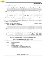
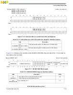
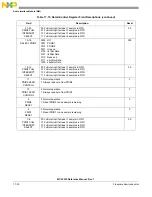
illustrates the valid bits in the EBU2Config Register and
provides the description
of the bit fields.
Figure 17-8. EBU2Config Register
1–0
U SOURCE SELECT
00 No embedded U channel
01 U channel from IEC958 receive block. (CD mode)
10 Reserved, undefined
11 U channel from on-chip U channel transmitter.
00
4
1
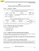
The IEC958 interface needs 64 * audio sample frequency clock for good operation. This is 2.822 MHz for operation at a
sample rate of 44.1 kHz.
2
When The IEC958 transmitter is set to follow SCLK1, SCLK2, SCLK3, or SCLK4, it will transmit at the same rate as the serial
audio interface only if the interface uses 64 bit clocks / word clock format.
3
When bit 11 is set, the FIFO is in its reset condition. The FIFO is always re-set to “contain 1 sample”. This sample value is
re-set at the same time to “all-zeros”.
4
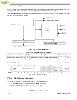
U channel selection is described on section handling subcode processing.
5
Before starting IEC958 transmission to copy data from another incoming channel, first reset the FIFO to one sample
remaining, while the source selector is set to correct source. When the FIFO is switched to normal operation, transmission
will start normally.
6
Digital zero means data transmitted is digital zero, while “C” and “U” channel contain valid data. When digital zero is
transmitted, the IEC958 transmit FIFO is not read any more by the IEC958 transmit hardware.
7
PDOR1, PDOR2, PDOR3: Processor Data Out Register.
8
Reprogramming bits 15-12 during functional operation is not allowed. Reprogramming is only allowed while FIFO is in its
reset condition (bit 11 set ‘1’)
9
When “digital zero” is selected as a source, the FIFO outputs “zero” on its outgoing data bus, regardless of the input side and
content of the FIFO. No FIFO related exceptions are generated.
10
This bit controls the outgoing validity flag of the EBU transmitter. When it is re-set, all outgoing data is flagged as “valid”. If it
is set, all data is flagged “invalid”.
11
When the FIFO leaves the reset state, because the user write a “normal operation” state into the control register, the FIFO
is kept into reset until first long-word is written to it. As a result, the “start” of the normal operation is synchronized with
the writing of the first data into the FIFO.
12
This field selects what is output on EBUOUT1. If the field is “000,” the SPDIF output is off and outputs 0. If the field is “001”
to “100,” it muxes out one of the EBUIN’s to the EBUOUT, without any reformatting. When the field is set to “101,” this is
normal operation of the SPDIF transmitter.
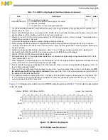
Address MBAR2 + 0xD0 (Reset 0x3f00)
Access: User read/write
31
30
29
28
27
26
25
24
23
22
21
20
19
18
17
16
R
W
Reset
0
0
0
0
0
0
0
0
0
0
0
0
0
0
0
0
15
14
13
12
11
10
9
8
7
6
5
4
3
2
1
0
R
IEC958 RECEIVE
SOUCE SELECT
W
Reset
0
0
1
1
1
1
1
1
0
0
00
0
0
0
0
0
Table 17-6. EBU1Config Register Field Descriptions (continued)
Field
Description
Reset
Notes
Summary of Contents for MCF5253
Page 1: ...Document Number MCF5253RM Rev 1 08 2008 MCF5253 Reference Manual...
Page 26: ...MCF5253 Reference Manual Rev 1 xxvi Freescale Semiconductor...
Page 32: ...MCF5253 Reference Manual Rev 1 xxxii Freescale Semiconductor...
Page 46: ...MCF5253 Introduction MCF5253 Reference Manual Rev 1 1 14 Freescale Semiconductor...
Page 62: ...Signal Description MCF5253 Reference Manual Rev 1 2 16 Freescale Semiconductor...
Page 98: ...Instruction Cache MCF5253 Reference Manual Rev 1 5 10 Freescale Semiconductor...
Page 104: ...Static RAM SRAM MCF5253 Reference Manual Rev 1 6 6 Freescale Semiconductor...
Page 128: ...Synchronous DRAM Controller Module MCF5253 Reference Manual Rev 1 7 24 Freescale Semiconductor...
Page 144: ...Bus Operation MCF5253 Reference Manual Rev 1 8 16 Freescale Semiconductor...
Page 176: ...System Integration Module SIM MCF5253 Reference Manual Rev 1 9 32 Freescale Semiconductor...
Page 198: ...Analog to Digital Converter ADC MCF5253 Reference Manual Rev 1 12 6 Freescale Semiconductor...
Page 246: ...DMA Controller MCF5253 Reference Manual Rev 1 14 18 Freescale Semiconductor...
Page 282: ...UART Modules MCF5253 Reference Manual Rev 1 15 36 Freescale Semiconductor...
Page 344: ...Audio Interface Module AIM MCF5253 Reference Manual Rev 1 17 46 Freescale Semiconductor...
Page 362: ...I2 C Modules MCF5253 Reference Manual Rev 1 18 18 Freescale Semiconductor...
Page 370: ...Boot ROM MCF5253 Reference Manual Rev 1 19 8 Freescale Semiconductor...