


Universal Serial Bus Interface
MCF5253 Reference Manual, Rev. 1
Freescale Semiconductor
24-77
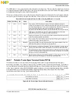
will automatically execute the value of Mult transactions. The host controller will not execute all Mult
transactions if:
•
The endpoint is an OUT and Transaction
n
Length goes to zero before all the Mult transactions
have executed (ran out of data), or
•
The endpoint is an IN and the endpoint delivers a short packet, or an error occurs on a transaction
before Mult transactions have been executed. The end of micro-frame may occur before all of the
transaction opportunities have been executed. When this happens, the transfer state of the transfer
description is advanced to reflect the progress that was made, the result written back to the iTD and
the host controller proceeds to processing the next micro-frame.
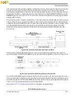
24.9.8.2
Software Operational Model for iTDs
A client buffer request to an isochronous endpoint may span 1 to N micro-frames. When N is larger than
one, the system software may have to use multiple iTDs to read or write data with the buffer (if N is larger
than eight, it must use more than one iTD).
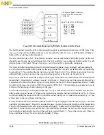
illustrates the simple model of how a client buffer is mapped by the system software to the
periodic schedule (that is, the periodic frame list and a set of iTDs). On the right is the client description
of its request. The description includes a buffer base address plus additional annotations to identify which
portions of the buffer should be used with each bus transaction. In the middle is the iTD data structures
used by the system software to service the client request. Each iTD can be initialized to service up to 24
transactions, organized into eight groups of up to three transactions each. Each group maps to one
micro-frame's worth of transactions. The EHCI controller does not provide per-transaction results within
a micro-frame. It treats the per-micro-frame transactions as a single logical transfer. On the left is the host
controller’s frame list. The system software establishes references from the appropriate locations in the
frame list to each of the appropriate iTDs. If the buffer is large, then the system software can use a small
set of iTDs to service the entire buffer. The system software can activate the transaction description records
(contained in each iTD) in any pattern required for the particular data stream.
Summary of Contents for MCF5253
Page 1: ...Document Number MCF5253RM Rev 1 08 2008 MCF5253 Reference Manual...
Page 26: ...MCF5253 Reference Manual Rev 1 xxvi Freescale Semiconductor...
Page 32: ...MCF5253 Reference Manual Rev 1 xxxii Freescale Semiconductor...
Page 46: ...MCF5253 Introduction MCF5253 Reference Manual Rev 1 1 14 Freescale Semiconductor...
Page 62: ...Signal Description MCF5253 Reference Manual Rev 1 2 16 Freescale Semiconductor...
Page 98: ...Instruction Cache MCF5253 Reference Manual Rev 1 5 10 Freescale Semiconductor...
Page 104: ...Static RAM SRAM MCF5253 Reference Manual Rev 1 6 6 Freescale Semiconductor...
Page 128: ...Synchronous DRAM Controller Module MCF5253 Reference Manual Rev 1 7 24 Freescale Semiconductor...
Page 144: ...Bus Operation MCF5253 Reference Manual Rev 1 8 16 Freescale Semiconductor...
Page 176: ...System Integration Module SIM MCF5253 Reference Manual Rev 1 9 32 Freescale Semiconductor...
Page 198: ...Analog to Digital Converter ADC MCF5253 Reference Manual Rev 1 12 6 Freescale Semiconductor...
Page 246: ...DMA Controller MCF5253 Reference Manual Rev 1 14 18 Freescale Semiconductor...
Page 282: ...UART Modules MCF5253 Reference Manual Rev 1 15 36 Freescale Semiconductor...
Page 344: ...Audio Interface Module AIM MCF5253 Reference Manual Rev 1 17 46 Freescale Semiconductor...
Page 362: ...I2 C Modules MCF5253 Reference Manual Rev 1 18 18 Freescale Semiconductor...
Page 370: ...Boot ROM MCF5253 Reference Manual Rev 1 19 8 Freescale Semiconductor...


