5: BASIC OPERATION
LMV1000 (G)(E) AIR-COOLED LASER MARKER
5-4
990-541
Referring to the list below, adjust the distance between the f
ș
lens and the workpiece.
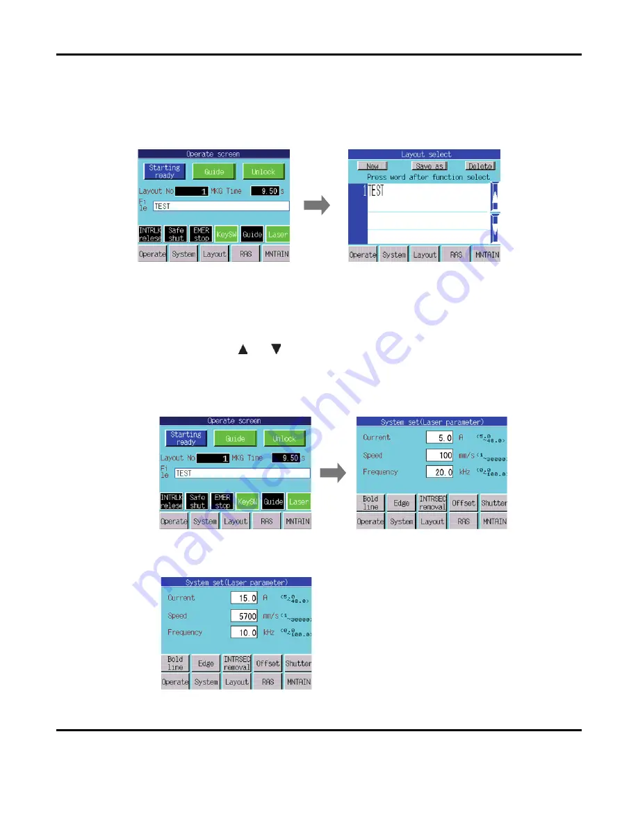
2. Selecting the File Name
Select the row labeled
File
on the
Operate
Screen
to select the file name. Once selected, the
Layout Select
screen will appear.
In the figure on the previous page, a layout file named
TEST
is registered as the layout number
1
(see
Creating and Saving Layout File
for information on saving a design layout).
Press the layout file name you want to load on the
Layout Select
screen. When five or more
layout files are registered, they all cannot be displayed at the same time. Scroll through the
filenames by selecting the
and
buttons on the right side of the screen
.
3. Setting a Marking Condition
a.
Press the
System
button to access the
System Set (Laser parameter)
screen.
b.
Set the LD Current, Marking Speed and Cycle (Q-switch) Frequency.
Set the conditions for the workpiece. Once
the marking condition values are set, the
Laser will mark the workpiece with the
entered values.
Summary of Contents for LMV1000
Page 8: ...LMV1000 G E AIR COOLED LASER MARKER viii 990 541...
Page 9: ...LMV1000 G E AIR COOLED LASER MARKER 990 541 ix...
Page 17: ......
Page 35: ......
Page 47: ......
Page 215: ...8 COMMUNICATION FUNCTION OPTION LMV1000 G E AIR COOLED LASER MARKER 8 14 990 541...
Page 231: ......
Page 237: ......
Page 239: ...11 OUTLINE DIMENSIONS LMV1000 G E AIR COOLED LASER MARKER 11 2 990 541 Oscillator Continued...
Page 241: ...11 OUTLINE DIMENSIONS LMV1000 G E AIR COOLED LASER MARKER 11 4 990 541 Oscillator 1 2 3 4...
Page 243: ......
Page 259: ......


