


Advanced functions
107
A
dv
an
ce
d
Fu
nc
tio
ns
value may reduce the nominal error. If the value is reduced, response will be faster but
setting too low may lead to controller oscillation.
►
H53: Set the output value to the variation of the error. The error is detected by 0.01 sec
in SV-iG5H. If differential time is set to 0.01 sec and the percentage variation of error
per 1 sec is 100%, 1% per 10msec is output.
►
H54: PID Feed Forward Gain. Set the gain to add the target value to the PID controller
output.
►
H55, H56: It limits the output of the PID controller.
►
H57: selects PID Reference
►
H58: PID Reference and PID feedback
’s units are classified as two which is [Hz] and
[%]. H58=0: [Hz], H58=1: [%]
►
H59 : [PID Out Inverse] sets PID controller
’s output Invert.
►
I17 - I20: To exchange PID to normal operation, set one of P1-P4 terminal to 21 and
turn ON.
►
rPM: Calculates the feedback from H50 into Motor frequency and displays it.
►
rEF: indicates PID controller
’s command value.
►
Fbk: converts feedback amount set in H50 to motor frequency.
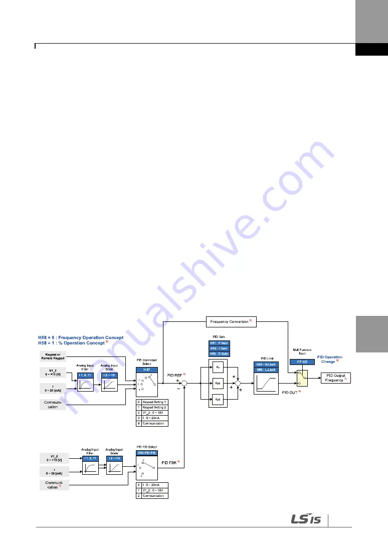
PID control diagram
8.7.1
Normal PID drive (H54=0)
Summary of Contents for SV-iG5H Series
Page 1: ...Thank you for purchasing LS Variable Frequency Drives ...
Page 14: ......
Page 23: ...9 Installation Wiring Installation 2 3 Terminal wiring Control I O ...
Page 24: ...10 Installation Wiring ...
Page 51: ...37 Programming Keypad Basic operation Basic Ops Wiring Operating pattern ...
Page 174: ...Protective functions 160 ...
Page 220: ...206 DECLARATION OF CONFIRMITY ...
Page 224: ...210 ...