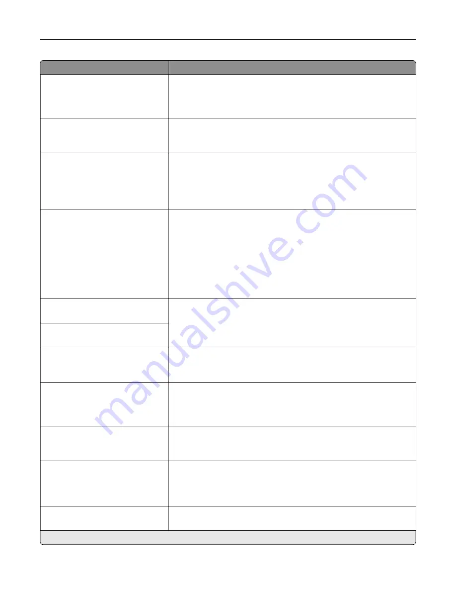
Menu item
Description
Symbol Set
[List of available symbol set] (10U
PC
‑
8*)
Specify the symbol set for each font name.
Note:
A symbol set is a set of alphabetic and numeric characters,
punctuation, and special symbols. Symbol sets support the different
languages or specific programs such as math symbols for scientific text.
Pitch
0.08–100.00 (10.00*)
Specify the pitch for fixed or monospaced fonts.
Note:
Pitch refers to the number of fixed
‑
space characters in a horizontal
inch of type.
Orientation
Portrait*
Landscape
Reverse Portrait
Reverse Landscape
Specify the orientation of text and graphics on the page.
Lines per Page
1–255
Specify the number of lines of text for each page printed through the PCL®
data stream.
Notes:
•
This menu item activates vertical escapement that causes the
selected number of requested lines to print between the default
margins of the page.
•
60 is the U.S. factory default setting. 64 is the international factory
default setting.
PCL5 Minimum Line Width
1–30 (2*)
Set the initial minimum stroke width.
PCLXL Minimum Line Width
1–30 (2*)
A4 Width
198 mm*
203 mm
Set the width of the logical page on A4
‑
size paper.
Note:
Logical page is the space on the physical page where data is
printed.
Auto CR after LF
On
Off*
Set the printer to perform a carriage return after a line feed control
command.
Note:
Carriage return is a mechanism that commands the printer to move
the position of the cursor to the first position on the same line.
Auto LF after CR
On
Off*
Set the printer to perform a line feed after a carriage return control
command.
Tray Renumber
Assign Tray [x]
Assign Manual Paper
Assign Manual Envelope
Configure the printer to work with a different print driver or custom
application that uses a different set of source assignments to request a
given paper source.
Tray Renumber
View Factory Defaults
Show the factory default value assigned for each paper source.
Note:
An asterisk (*) next to a value indicates the factory default setting.
Use printer menus
139
Summary of Contents for XC4342
Page 64: ...3 Remove the fax cover 4 Remove the fax bracket Set up install and configure 64 ...
Page 65: ...5 Install the fax card to the bracket Set up install and configure 65 ...
Page 70: ...4 Install the ISP into its housing Set up install and configure 70 ...
Page 71: ...5 Attach the housing to the controller board shield Set up install and configure 71 ...
Page 76: ...Set up install and configure 76 ...
Page 84: ...Set up install and configure 84 ...
Page 85: ...3 Install the wireless module into its housing Set up install and configure 85 ...
Page 86: ...4 Attach the wireless module to the controller board shield Set up install and configure 86 ...
Page 88: ...6 Attach the controller board shield Set up install and configure 88 ...
Page 205: ...2 Remove the used toner cartridge 3 Unpack the new toner cartridge Maintain the printer 205 ...
Page 206: ...4 Insert the new toner cartridge 5 Close door B Maintain the printer 206 ...
Page 207: ...Replacing the black imaging unit 1 Open door B Maintain the printer 207 ...
Page 209: ...3 Remove the toner cartridges Maintain the printer 209 ...
Page 210: ...4 Disconnect the imaging kit cable Maintain the printer 210 ...
Page 214: ...9 Insert the imaging kit Maintain the printer 214 ...
Page 216: ...Replacing the color imaging kit 1 Open door B Maintain the printer 216 ...
Page 218: ...3 Remove the toner cartridges Maintain the printer 218 ...
Page 219: ...4 Disconnect the imaging kit cable Maintain the printer 219 ...
Page 220: ...5 Remove the used imaging kit Maintain the printer 220 ...
Page 222: ...8 Insert the black imaging unit into the new imaging kit Maintain the printer 222 ...
Page 223: ...9 Insert the new imaging kit Maintain the printer 223 ...
Page 225: ...Replacing the waste toner bottle 1 Open door B Maintain the printer 225 ...
Page 238: ...2 Remove the used ADF pick roller Maintain the printer 238 ...
Page 240: ...5 Insert the new ADF separator roller until it clicks into place Maintain the printer 240 ...
Page 250: ...2 Remove the ADF pick roller Maintain the printer 250 ...
Page 252: ...5 Insert the ADF separator roller until it clicks into place Maintain the printer 252 ...


