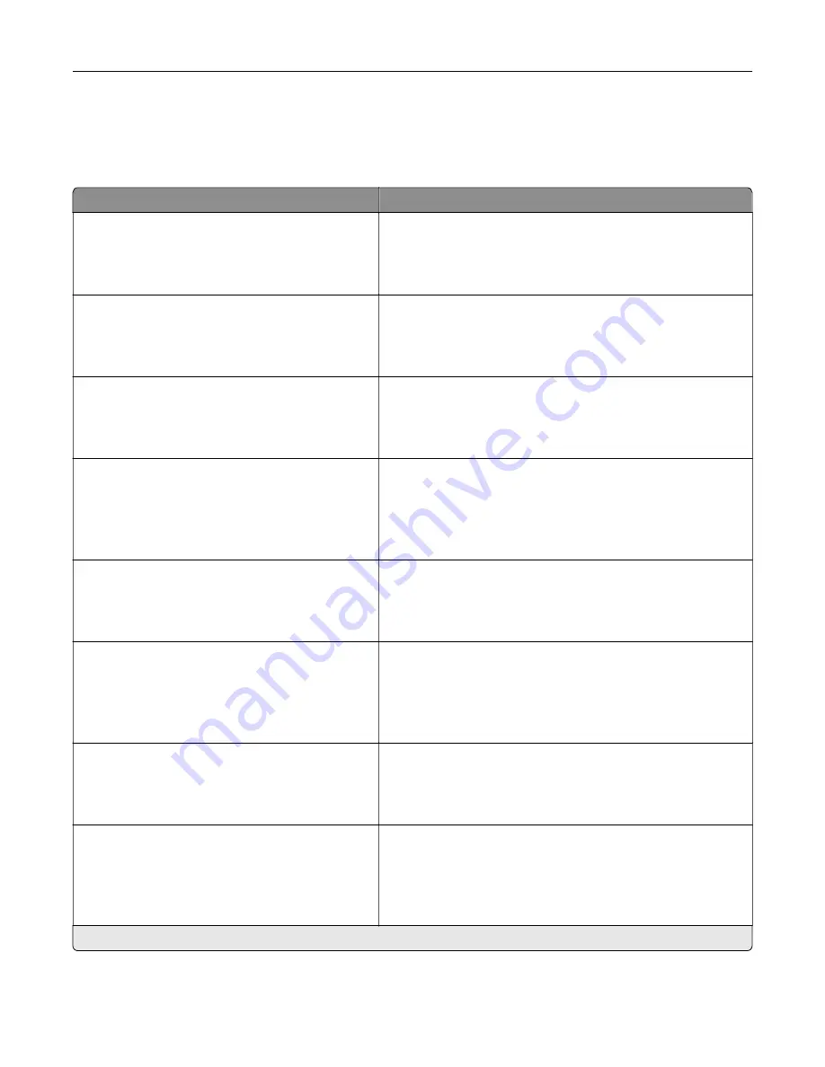
Maintenance
Configuration Menu
Menu item
Description
USB Configuration
USB PnP
1*
2
Change the USB driver mode of the printer to improve its
compatibility with a personal computer.
USB Configuration
USB Scan to Local
On*
Off
Set whether the USB device driver enumerates as a USB
Simple device (single interface) or as a USB Composite device
(multiple interfaces).
USB Configuration
USB Speed
Full
Auto*
Set the USB port to run at full speed and disable its high
‑
speed
capabilities.
Tray Configuration
Size Sensing
Tray [x] Sensing
Off
On*
Set the tray to sense automatically the paper size loaded into
it.
Tray Configuration
Tray Linking
Automatic*
Off
Set the printer to link the trays that have the same paper type
and paper size settings.
Tray Configuration
Show Tray Insert Message
Off
Only for unknown sizes*
Always
Display a message that lets the user change the paper size and
paper type settings after inserting the tray.
Tray Configuration
A5 Loading
Short Edge
Long Edge*
Determine the default loading orientation for the A5 size paper
in all paper sources.
Tray Configuration
Paper Prompts
Auto*
Multipurpose Feeder
Manual Paper
Set the paper source that the user fills when a prompt to load
paper appears.
Note:
For Multipurpose Feeder to appear, in the Paper menu,
set Configure MP to Cassette.
Note:
An asterisk (*) next to a value indicates the factory default setting.
Use printer menus
126
Summary of Contents for XC4342
Page 64: ...3 Remove the fax cover 4 Remove the fax bracket Set up install and configure 64 ...
Page 65: ...5 Install the fax card to the bracket Set up install and configure 65 ...
Page 70: ...4 Install the ISP into its housing Set up install and configure 70 ...
Page 71: ...5 Attach the housing to the controller board shield Set up install and configure 71 ...
Page 76: ...Set up install and configure 76 ...
Page 84: ...Set up install and configure 84 ...
Page 85: ...3 Install the wireless module into its housing Set up install and configure 85 ...
Page 86: ...4 Attach the wireless module to the controller board shield Set up install and configure 86 ...
Page 88: ...6 Attach the controller board shield Set up install and configure 88 ...
Page 205: ...2 Remove the used toner cartridge 3 Unpack the new toner cartridge Maintain the printer 205 ...
Page 206: ...4 Insert the new toner cartridge 5 Close door B Maintain the printer 206 ...
Page 207: ...Replacing the black imaging unit 1 Open door B Maintain the printer 207 ...
Page 209: ...3 Remove the toner cartridges Maintain the printer 209 ...
Page 210: ...4 Disconnect the imaging kit cable Maintain the printer 210 ...
Page 214: ...9 Insert the imaging kit Maintain the printer 214 ...
Page 216: ...Replacing the color imaging kit 1 Open door B Maintain the printer 216 ...
Page 218: ...3 Remove the toner cartridges Maintain the printer 218 ...
Page 219: ...4 Disconnect the imaging kit cable Maintain the printer 219 ...
Page 220: ...5 Remove the used imaging kit Maintain the printer 220 ...
Page 222: ...8 Insert the black imaging unit into the new imaging kit Maintain the printer 222 ...
Page 223: ...9 Insert the new imaging kit Maintain the printer 223 ...
Page 225: ...Replacing the waste toner bottle 1 Open door B Maintain the printer 225 ...
Page 238: ...2 Remove the used ADF pick roller Maintain the printer 238 ...
Page 240: ...5 Insert the new ADF separator roller until it clicks into place Maintain the printer 240 ...
Page 250: ...2 Remove the ADF pick roller Maintain the printer 250 ...
Page 252: ...5 Insert the ADF separator roller until it clicks into place Maintain the printer 252 ...


