


3-25
BUS OVERVIEW
The diagnostic signals group shown in Table 3-19 provides signals for probing the Pentium Pro
processor, monitoring Pentium Pro processor performance, and implementing an IEEE 1149.1
boundary scan.
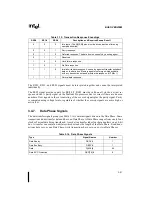
PM[1:0]# are the Performance Monitor signals. These signals are outputs from the Pentium Pro
processor that indicate the status of four programmable counters for monitoring Pentium Pro
processor performance.
TCK is the Test Clock, used to clock activity on the five-signal Test Access Port (TAP). TDI is
the Test Data In signal, transferring serial test data into the Pentium Pro processor. TDO is the
Test Data Out signal, transferring serial test data out of the Pentium Pro processor. TMS is used
to control the sequence of TAP controller state changes. TRST# is used to asynchronously ini-
tialize the TAP controller.
3.4.11.
Power, Ground, and Reserved Pins
The Pentium Pro processor bus and Pentium Pro processor dedicate many pins to power and
ground signals. Refer to Chapter 15, Mechanical Specifications for the pin assignment.
Summary of Contents for Pentium Pro Family
Page 17: ...1 Component Introduction ...
Page 26: ...2 Pentium Pro Processor Architecture Overview ...
Page 27: ......
Page 36: ...3 Bus Overview ...
Page 62: ...4 Bus Protocol ...
Page 105: ...5 Bus Transactions and Operations ...
Page 126: ...6 Range Registers ...
Page 131: ...7 Cache Protocol ...
Page 135: ...8 Data Integrity ...
Page 148: ...9 Configuration ...
Page 161: ...10 Pentium Pro Processor Test Access Port TAP ...
Page 172: ...11 Electrical Specifications ...
Page 201: ...12 GTL Interface Specification ...
Page 229: ...13 3 3V Tolerant Signal Quality Specifications ...
Page 233: ...14 Thermal Specifications ...
Page 239: ...15 Mechanical Specifications ...
Page 241: ...15 2 MECHANICAL SPECIFICATIONS s Figure 15 1 Package Dimensions Bottom View ...
Page 252: ...16 Tools ...
Page 260: ...16 8 TOOLS Figure 16 4 Generic MP System Layout for Debug Port Connection ...
Page 264: ...17 OverDrive Processor Socket Specification ...
Page 290: ...A Signals Reference ...
Page 320: ...Index ...
Page 328: ......