


14-4
THERMAL SPECIFICATIONS
14.2.
THERMAL ANALYSIS
Table 14-1 below lists the case-to-ambient thermal resistances of the Pentium Pro processor for
different air flow rates and heat sink heights.
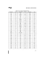
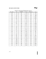
Table 14-2 shows the TA required given a 29.2W processor (150 MHz, 256K cache), and a TC
of 85
°
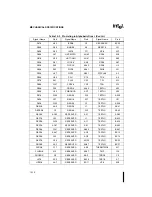
C. Table 14-3 shows the TA required assuming a 40W processor. Table 14-2 and Table
14-3 were produced by using the relationships of Section 14.1.3., “Thermal Resistance” and the
data of Table 14-1.
NOTES:
1. All data taken at sea level. For altitudes above sea level, it is recommended that a derating factor of
1°C/1000 feet be used.
2. Heat Sink: 2.235” square omni-directional pin, aluminum heat sink with a pin thickness of 0.085”, a pin
spacing of 0.13” and a base thickness of 0.15”. See Figure 14-4. A thin layer of thermal grease (Thermo-
set TC208 with thermal conductivity of 1.2W/m-°K) was used as the interface material between the heat
sink and the package.
Table 14-1. Case-To-Ambient Thermal Resistance
Θ
CA [
°
C/W] vs. Airflow [Linear Feet per Minute] and Heat Sink Height1
Airflow (LFM):
100
200
400
600
800
1000
With 0.5” Heat Sink 2
—
3.16
2.04
1.66
1.41
1.29
With 1.0” Heat Sink 2
2.55
1.66
1.08
0.94
0.80
0.76
With 1.5” Heat Sink 2
1.66
1.31
0.90
0.78
0.71
0.67
With 2.0” Heat Sink 2
1.47
1.23
0.87
0.75
0.69
0.65
Figure 14-4. Analysis Heat Sink Dimensions
0.085”
0.130”
Height
0.150”
2.235”
Summary of Contents for Pentium Pro Family
Page 17: ...1 Component Introduction ...
Page 26: ...2 Pentium Pro Processor Architecture Overview ...
Page 27: ......
Page 36: ...3 Bus Overview ...
Page 62: ...4 Bus Protocol ...
Page 105: ...5 Bus Transactions and Operations ...
Page 126: ...6 Range Registers ...
Page 131: ...7 Cache Protocol ...
Page 135: ...8 Data Integrity ...
Page 148: ...9 Configuration ...
Page 161: ...10 Pentium Pro Processor Test Access Port TAP ...
Page 172: ...11 Electrical Specifications ...
Page 201: ...12 GTL Interface Specification ...
Page 229: ...13 3 3V Tolerant Signal Quality Specifications ...
Page 233: ...14 Thermal Specifications ...
Page 239: ...15 Mechanical Specifications ...
Page 241: ...15 2 MECHANICAL SPECIFICATIONS s Figure 15 1 Package Dimensions Bottom View ...
Page 252: ...16 Tools ...
Page 260: ...16 8 TOOLS Figure 16 4 Generic MP System Layout for Debug Port Connection ...
Page 264: ...17 OverDrive Processor Socket Specification ...
Page 290: ...A Signals Reference ...
Page 320: ...Index ...
Page 328: ......