


11-11
ELECTRICAL SPECIFICATIONS
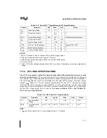
11.9.
PWRGOOD
PWRGOOD is a 3.3V tolerant input. It is expected that this signal will be a clean indication that
clocks and the 3.3V, 5V and VccP supplies are stable and within their specifications. Clean im-
plies that the signal will remain low, (capable of sinking leakage current) without glitches, from
the time that the power supplies are turned on until they come within specification. The signal
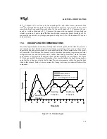
will then transition monotonically to a high (3.3V) state. Figure 11-5 illustrates the relationship
of PWRGOOD to other system signals. PWRGOOD can be driven inactive at any time, but
power and clocks must again be stable before the rising edge of PWRGOOD. It must also meet
the minimum pulse width specification in Table 11-13 and be followed by a 1mS RESET# pulse.
This signal must be supplied to the Pentium Pro processor as it is used to protect internal circuits
against voltage sequencing issues. Use of this signal is recommended for added reliability.
This signal does not need to be synchronized for FRC operation. It should be high throughout
boundary scan testing.
11.10. THERMTRIP#
The Pentium Pro processor protects itself from catastrophic overheating by use of an internal
thermal sensor. This sensor is set well above the normal operating temperature to ensure that
there are no false trips. The processor will stop all execution when the junction temperature ex-
ceeds ~135
°
C. This is signaled to the system by the THERMTRIP# pin. Once activated, the sig-
nal remains latched, and the processor stopped, until RESET# goes active. There is no hysteresis
built into the thermal sensor itself, so as long as the die temperature drops below the trip level,
a RESET# pulse will reset the processor and execution will continue. If the temperature has not
dropped beyond the trip level, the processor will continue to drive THERMTRIP# and remain
stopped.
Figure 11-5. PWRGOOD Relationship at Power-On
Summary of Contents for Pentium Pro Family
Page 17: ...1 Component Introduction ...
Page 26: ...2 Pentium Pro Processor Architecture Overview ...
Page 27: ......
Page 36: ...3 Bus Overview ...
Page 62: ...4 Bus Protocol ...
Page 105: ...5 Bus Transactions and Operations ...
Page 126: ...6 Range Registers ...
Page 131: ...7 Cache Protocol ...
Page 135: ...8 Data Integrity ...
Page 148: ...9 Configuration ...
Page 161: ...10 Pentium Pro Processor Test Access Port TAP ...
Page 172: ...11 Electrical Specifications ...
Page 201: ...12 GTL Interface Specification ...
Page 229: ...13 3 3V Tolerant Signal Quality Specifications ...
Page 233: ...14 Thermal Specifications ...
Page 239: ...15 Mechanical Specifications ...
Page 241: ...15 2 MECHANICAL SPECIFICATIONS s Figure 15 1 Package Dimensions Bottom View ...
Page 252: ...16 Tools ...
Page 260: ...16 8 TOOLS Figure 16 4 Generic MP System Layout for Debug Port Connection ...
Page 264: ...17 OverDrive Processor Socket Specification ...
Page 290: ...A Signals Reference ...
Page 320: ...Index ...
Page 328: ......