


11-23
ELECTRICAL SPECIFICATIONS
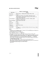
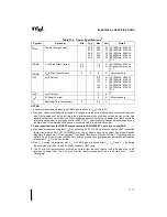
NOTES:
1. Not 100% tested. Guaranteed by design/characterization.
2. 1ns can be added to the maximum TCK rise and fall times for every 1MHz below 16MHz.
3. Referenced to TCK rising edge.
4. Referenced to TCK falling edge.
5. Valid delay timing for this signal is specified into 150
Ω
terminated to 3.3V.
6. Non-Test Outputs and Inputs are the normal output or input signals (besides TCK, TRST#, TDI, TDO and
TMS). These timings correspond to the response of these signals due to boundary scan operations.
PWRGOOD should be driven high throughout boundary scan testing.
7. During Debug Port operation, use the normal specified timings rather than the boundary scan timings.
Table 11-16. Boundary Scan Interface A.C. Specifications
T#
Parameter
Min
Max
Unit
Figure
Notes
T30: TCK Frequency
—
16
MHz
T31: TCK Period
62.5
—
ns
11-7
T32: TCK High Time
25
ns
11-7
@2.0V, 1
T33: TCK Low Time
25
ns
11-7
@0.8V, 1
T34: TCK Rise Time
5
ns
11-7
(0.8V-2.0V), 1, 2
T35: TCK Fall Time
5
ns
11-7
(2.0V-0.8V), 1, 2
T36: TRST# Pulse Width
40
ns
11-15
1, Asynchronous
T37: TDI, TMS Setup Time
5
ns
11-14
3
T38: TDI, TMS Hold Time
14
ns
11-14
3
T39: TDO Valid Delay
1
10
ns
11-14
4, 5
T40: TDO Float Delay
25
ns
11-14
1, 4, 5
T41: All Non-Test Outputs Valid Delay
2
25
ns
11-14
4, 6, 7
T42: All Non-Test Outputs Float Delay
25
ns
11-14
1, 4, 6, 7
T43: All Non-Test Inputs Setup Time
5
ns
11-14
3, 6, 7
T44: All Non-Test Inputs Hold Time
13
ns
11-14
3, 6, 7
Summary of Contents for Pentium Pro Family
Page 17: ...1 Component Introduction ...
Page 26: ...2 Pentium Pro Processor Architecture Overview ...
Page 27: ......
Page 36: ...3 Bus Overview ...
Page 62: ...4 Bus Protocol ...
Page 105: ...5 Bus Transactions and Operations ...
Page 126: ...6 Range Registers ...
Page 131: ...7 Cache Protocol ...
Page 135: ...8 Data Integrity ...
Page 148: ...9 Configuration ...
Page 161: ...10 Pentium Pro Processor Test Access Port TAP ...
Page 172: ...11 Electrical Specifications ...
Page 201: ...12 GTL Interface Specification ...
Page 229: ...13 3 3V Tolerant Signal Quality Specifications ...
Page 233: ...14 Thermal Specifications ...
Page 239: ...15 Mechanical Specifications ...
Page 241: ...15 2 MECHANICAL SPECIFICATIONS s Figure 15 1 Package Dimensions Bottom View ...
Page 252: ...16 Tools ...
Page 260: ...16 8 TOOLS Figure 16 4 Generic MP System Layout for Debug Port Connection ...
Page 264: ...17 OverDrive Processor Socket Specification ...
Page 290: ...A Signals Reference ...
Page 320: ...Index ...
Page 328: ......