


9-8
CONFIGURATION
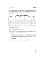
If FRC is used, then two physical processors are combined to create a single logical processor.
Processors with agent ID 0 and 2 are designated as FRC-masters and use their agent ID as their
parallel bus arbitration ID. Processors with agent ID 1 and 3 are designated as FRC checkers for
processors 0 and 2 respectively and assume the characteristics of their respective masters as
shown in Table 9-3.
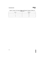
NOTE:
1. L and H designate electrical levels.
9.1.19.
Low Power Standby Enable
A configuration register bit which enables distribution of the core clock during AUTOHalt and
Stop Grant mode has been included in the power-on configuration register. This register will
support bit D26, which can be read and written by software.
— D26=1
In this mode when the Pentium Pro processor enters AUTOHalt or Stop Grant, it will
not distribute a clock to its core units. This allows the Pentium Pro processor to reduce
its standby power consumption, but large current transients are produced upon entering
and exiting this mode.
— D26=0 (Default)
In this mode, AUTOHalt and Stop Grant will not stop internal clock distribution. The
Pentium Pro processor will have higher standby power consumption, but will produce
smaller current transients on entering and exiting this mode.
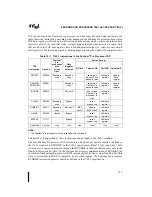
Table 9-3. Arbitration ID Configuration
BR0#
BR1#
BR2#
BR3#
A5#
Arb Id
L1
H
H
H
H
0
H
H
H
L
L
1
H
H
L
H
H
2
H
L
H
H
H
3
L
H
H
H
L
0
H
H
H
L
L
0
H
H
L
H
L
2
H
L
H
H
L
2
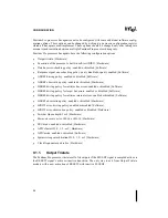
Summary of Contents for Pentium Pro Family
Page 17: ...1 Component Introduction ...
Page 26: ...2 Pentium Pro Processor Architecture Overview ...
Page 27: ......
Page 36: ...3 Bus Overview ...
Page 62: ...4 Bus Protocol ...
Page 105: ...5 Bus Transactions and Operations ...
Page 126: ...6 Range Registers ...
Page 131: ...7 Cache Protocol ...
Page 135: ...8 Data Integrity ...
Page 148: ...9 Configuration ...
Page 161: ...10 Pentium Pro Processor Test Access Port TAP ...
Page 172: ...11 Electrical Specifications ...
Page 201: ...12 GTL Interface Specification ...
Page 229: ...13 3 3V Tolerant Signal Quality Specifications ...
Page 233: ...14 Thermal Specifications ...
Page 239: ...15 Mechanical Specifications ...
Page 241: ...15 2 MECHANICAL SPECIFICATIONS s Figure 15 1 Package Dimensions Bottom View ...
Page 252: ...16 Tools ...
Page 260: ...16 8 TOOLS Figure 16 4 Generic MP System Layout for Debug Port Connection ...
Page 264: ...17 OverDrive Processor Socket Specification ...
Page 290: ...A Signals Reference ...
Page 320: ...Index ...
Page 328: ......