


16-2
TOOLS
16.2.1.
Primary Function
The primary function of an ITP is to provide a control and query interface for up to four Pentium
Pro processors in one cluster. With an ITP you can control program execution and have the abil-
ity to access processor registers, system memory and I/O. Thus, you can start and stop program
execution using a variety of breakpoints, single-step your program at the assembly code level,
as well as read and write registers, memory and I/O.
16.2.2.
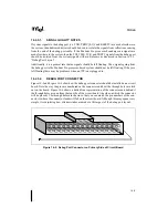
Debug Port Connector Description
An ITP will connect to the Pentium Pro processor system through the debug port. Intel recom-
mended connectors, to mate an ITP cable with the debug port on your board, are available in
either a vertical or right-angle configuration. Both configurations fit into the same board foot-
print. The connectors are manufactured by AMP Incorporated and are in their AMPMODU
System 50 line. Following are the AMP part numbers for the two connectors:
•
Amp 30-pin shrouded vertical header: 104068-3
•
Amp 30-pin shrouded right-angle header: 104069-5
NOTE
These are high density through hole connectors with pins on 0.050" by 0.100"
centers. Do not confuse these with the more common 0.100" by 0.100" center
headers.
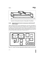
16.2.3.
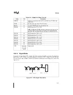
Debug Port Signal Descriptions
Table 16-1 describes the debug port signals and provides the pin assignment. The mechanical
pinout is shown in Section 16.2.5.2., “Debug Port Connector”.
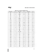
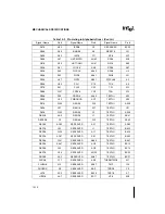
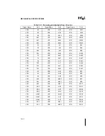
Table 16-1. Debug Port Pinout
Name
Pin
Description
RESET#
1
Reset signal from MP cluster to ITP. See signal note 1
DBRESET#
3
Open drain output from ITP to the system; should be tied into system
reset circuitry. This allows the ITP to reset the entire target system. See
signal note 2
TCK
5
Boundary scan signal from ITP to MP cluster
TMS
7
Boundary scan signal from ITP to MP cluster
TDI
8
Signal from ITP to first component in boundary scan chain of MP cluster
POWERON
9
From target Vtt to ITP (through a resistor). See signal note 3
TDO
10
Signal from last component in boundary scan chain of MP cluster to ITP
Summary of Contents for Pentium Pro Family
Page 17: ...1 Component Introduction ...
Page 26: ...2 Pentium Pro Processor Architecture Overview ...
Page 27: ......
Page 36: ...3 Bus Overview ...
Page 62: ...4 Bus Protocol ...
Page 105: ...5 Bus Transactions and Operations ...
Page 126: ...6 Range Registers ...
Page 131: ...7 Cache Protocol ...
Page 135: ...8 Data Integrity ...
Page 148: ...9 Configuration ...
Page 161: ...10 Pentium Pro Processor Test Access Port TAP ...
Page 172: ...11 Electrical Specifications ...
Page 201: ...12 GTL Interface Specification ...
Page 229: ...13 3 3V Tolerant Signal Quality Specifications ...
Page 233: ...14 Thermal Specifications ...
Page 239: ...15 Mechanical Specifications ...
Page 241: ...15 2 MECHANICAL SPECIFICATIONS s Figure 15 1 Package Dimensions Bottom View ...
Page 252: ...16 Tools ...
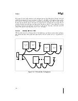
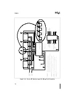
Page 260: ...16 8 TOOLS Figure 16 4 Generic MP System Layout for Debug Port Connection ...
Page 264: ...17 OverDrive Processor Socket Specification ...
Page 290: ...A Signals Reference ...
Page 320: ...Index ...
Page 328: ......