


5-1
CHAPTER 5
BUS TRANSACTIONS AND OPERATIONS
This chapter describes in detail the bus transactions and operations supported by the Pentium
Pro processor bus.
5.1.
BUS TRANSACTIONS SUPPORTED
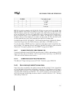
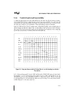
Figure 5-1 lists the different bus transactions.
The transactions classified as read data transactions normally expect a response initiated data
transfer from the agent addressed by the transaction. This is indicated by a Normal Data
Response in the Response Phase of the transaction. If no bytes are enabled, then a No Data Re-
sponse is returned by the addressed agent.
The transactions classified as write data transactions require request-initiated data transfer and
are identified by REQa[0]#. All responses except Normal Data Response are allowed. The target
asserts TRDY#. Implicit Writeback Responses may also occur and send additional snoop initi-
ated data.
Figure 5-1. Bus Transactions
All Bus Transactions
Memory
I/O Read
I/O Write
Branch Trace Message
Interrupt Acknowledge
I/O
Other
Mem Read
Mem Write
Flush
Halt
Sync
Flush Acknowledge
Stop Grant Acknowledge
SMI Acknowledge
Shutdown
Mem (Read) Invalidate LIne
Deferred Reply
Write data:
Read data:
No Data:
Deferred:
Summary of Contents for Pentium Pro Family
Page 17: ...1 Component Introduction ...
Page 26: ...2 Pentium Pro Processor Architecture Overview ...
Page 27: ......
Page 36: ...3 Bus Overview ...
Page 62: ...4 Bus Protocol ...
Page 105: ...5 Bus Transactions and Operations ...
Page 126: ...6 Range Registers ...
Page 131: ...7 Cache Protocol ...
Page 135: ...8 Data Integrity ...
Page 148: ...9 Configuration ...
Page 161: ...10 Pentium Pro Processor Test Access Port TAP ...
Page 172: ...11 Electrical Specifications ...
Page 201: ...12 GTL Interface Specification ...
Page 229: ...13 3 3V Tolerant Signal Quality Specifications ...
Page 233: ...14 Thermal Specifications ...
Page 239: ...15 Mechanical Specifications ...
Page 241: ...15 2 MECHANICAL SPECIFICATIONS s Figure 15 1 Package Dimensions Bottom View ...
Page 252: ...16 Tools ...
Page 260: ...16 8 TOOLS Figure 16 4 Generic MP System Layout for Debug Port Connection ...
Page 264: ...17 OverDrive Processor Socket Specification ...
Page 290: ...A Signals Reference ...
Page 320: ...Index ...
Page 328: ......