


3-11
BUS OVERVIEW
The INIT# input signal resets all Pentium Pro processor bus agents without affecting their inter-
nal (L1 or L2) caches or their floating-point registers. Each Pentium Pro processor begins exe-
cution at the address vector as defined during power on configuration. INIT# has another
meaning on RESET#’s active to inactive transition: if INIT# is sampled active on RESET#’s ac-
tive to inactive transition, then the Pentium Pro processor executes its built-in self test (BIST).
If the FLUSH# input signal is asserted, the Pentium Pro processor bus agent writes back all in-
ternal cache lines in the Modified state (L1 and L2 caches) and invalidates all internal cache
lines (L1 and L2 caches). The flush operation puts all internal cache lines in the Invalid state.
After all lines are written back and invalidated, the Pentium Pro processor drives a special trans-
action, the Flush Acknowledge transaction, to indicate completion of the flush operation. The
FLUSH# signal has a different meaning when it is sampled asserted on the active to inactive
transition of RESET#. If FLUSH# is sampled asserted on the active to inactive transition of RE-
SET#, then the Pentium Pro processor tristates all of its outputs. This function is used during
board testing.
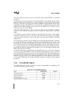
The Pentium Pro processor supplies a STPCLK# pin to enable the processor to enter a low pow-
er state. When STPCLK# is asserted, the Pentium Pro processor puts itself into the stop grant
state, issues a Stop Grant Acknowledge special transaction, and optionally stops providing in-
ternal clock signals to all units except the bus unit and the APIC unit. The processor continues
to snoop bus transactions while in stop grant state. When STPCLK# is deasserted, the processor
restarts its internal clock to all units and resumes execution. The assertion of STPCLK# has no
effect on the bus clock.
The PICCLK and PICD[1:0]# signals support the Advanced Programmable Interrupt Controller
(APIC) interface. The PICCLK signal is an input clock to the Pentium Pro processor for syn-
chronous operation of the APIC bus. The PICD[1:0]# signals are used for bidirectional serial
message passing on the APIC bus.
LINT[1:0] are local interrupt signals, also defined by the APIC interface. In APIC disabled
mode, LINT0 defaults to INTR, a maskable interrupt request signal. LINT1 defaults to NMI, a
non-maskable interrupt. Both signals are asynchronous inputs. In the APIC enable mode, LINT0
and LINT1 are defined with the local vector table.
LINT[1:0] are also used along with the A20M# and IGNNE# signals to determine the multiplier
for the internal clock frequency as described in Chapter 9, Configuration.
Summary of Contents for Pentium Pro Family
Page 17: ...1 Component Introduction ...
Page 26: ...2 Pentium Pro Processor Architecture Overview ...
Page 27: ......
Page 36: ...3 Bus Overview ...
Page 62: ...4 Bus Protocol ...
Page 105: ...5 Bus Transactions and Operations ...
Page 126: ...6 Range Registers ...
Page 131: ...7 Cache Protocol ...
Page 135: ...8 Data Integrity ...
Page 148: ...9 Configuration ...
Page 161: ...10 Pentium Pro Processor Test Access Port TAP ...
Page 172: ...11 Electrical Specifications ...
Page 201: ...12 GTL Interface Specification ...
Page 229: ...13 3 3V Tolerant Signal Quality Specifications ...
Page 233: ...14 Thermal Specifications ...
Page 239: ...15 Mechanical Specifications ...
Page 241: ...15 2 MECHANICAL SPECIFICATIONS s Figure 15 1 Package Dimensions Bottom View ...
Page 252: ...16 Tools ...
Page 260: ...16 8 TOOLS Figure 16 4 Generic MP System Layout for Debug Port Connection ...
Page 264: ...17 OverDrive Processor Socket Specification ...
Page 290: ...A Signals Reference ...
Page 320: ...Index ...
Page 328: ......