


11-3
ELECTRICAL SPECIFICATIONS
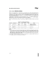
28 VccS inputs (3.3V) are for use by the on-package L2 Cache die of some processors. One
Vcc5 pin is provided for use by the fan of the OverDrive processor. Vcc5, VccS and VccP must
remain electrically separated from each other. On the circuit board, all VccP pins must be con-
nected to a voltage island and all VccS pins must be connected to a separate voltage island (an
island is a portion of a power plane that has been divided, or an entire plane). Similarly, all Vss
pins must be connected to a system ground plane. See Figure 15-3 for the locations of the power
and ground pins.
11.4.
DECOUPLING RECOMMENDATIONS
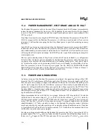
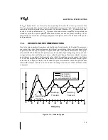
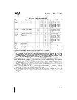
Due to the large number of transistors and high internal clock speeds, the Pentium Pro processor
can create large, short duration transient (switching) current surges that occur on internal clock
edges which can cause power planes to spike above and below their nominal value if not prop-
erly controlled. The Pentium Pro processor is also capable of generating large average current
swings between low and full power states, called Load-Change Transients, which can cause
power planes to sag below their nominal value if bulk decoupling is not adequate. See Figure
11-2 for an example of these current fluctuations. Care must be taken in the board design to guar-
antee that the voltage provided to the Pentium Pro processor remains within the specifications
listed in this volume. Failure to do so can result in timing violations or a reduced lifetime of the
component.
Figure 11-2. Transient Types
T ime (nS )
Vss Current
Vcc Current
Averaged Vcc Current
Load-Change
Transient
Switching
Transient
Switching
Transient
Summary of Contents for Pentium Pro Family
Page 17: ...1 Component Introduction ...
Page 26: ...2 Pentium Pro Processor Architecture Overview ...
Page 27: ......
Page 36: ...3 Bus Overview ...
Page 62: ...4 Bus Protocol ...
Page 105: ...5 Bus Transactions and Operations ...
Page 126: ...6 Range Registers ...
Page 131: ...7 Cache Protocol ...
Page 135: ...8 Data Integrity ...
Page 148: ...9 Configuration ...
Page 161: ...10 Pentium Pro Processor Test Access Port TAP ...
Page 172: ...11 Electrical Specifications ...
Page 201: ...12 GTL Interface Specification ...
Page 229: ...13 3 3V Tolerant Signal Quality Specifications ...
Page 233: ...14 Thermal Specifications ...
Page 239: ...15 Mechanical Specifications ...
Page 241: ...15 2 MECHANICAL SPECIFICATIONS s Figure 15 1 Package Dimensions Bottom View ...
Page 252: ...16 Tools ...
Page 260: ...16 8 TOOLS Figure 16 4 Generic MP System Layout for Debug Port Connection ...
Page 264: ...17 OverDrive Processor Socket Specification ...
Page 290: ...A Signals Reference ...
Page 320: ...Index ...
Page 328: ......