


17-12
OVERDRIVE® PROCESSOR SOCKET SPECIFICATION
OverDrive processor and the OEM VRM is NOT replaced with the OverDrive VRM,
the original voltage regulator will never enable its outputs because the lower voltage
OverDrive processor could be damaged. Refer to Figure 17-7.
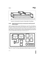
— Case 2: Header 8 AND alternate voltage source
If the system is designed with alternate voltage source and a Header 8 for future
upgrade support, then the UP# signal must be connected between Socket 8, Header 8,
and the alternate voltage source. The Pentium Pro processor voltage regulator should
use the UP# signal to disable the voltage output when detected low (indicating that an
OverDrive processor has been installed). The OverDrive VRM, when installed into the
Header 8 will use the UP# signal to enable its outputs (when detected low). When the
Pentium Pro processor is replaced with an OverDrive processor and the OverDrive
VRM is installed, the original voltage regulator must never enable its outputs because
the lower voltage OverDrive processor could be damaged. Refer to Figure 17-8.
Figure 17-7. Upgrade Presence Detect Schematic - Case 1
Figure 17-8. Upgrade Presence Detect Schematic - Case 2
Socket 8
UP#
+ 5 Volt
10 k
Ω
Header 8
On-Board VR
Socket 8
UP#
+ 5 Volt
10 k
Ω
Header 8
Summary of Contents for Pentium Pro Family
Page 17: ...1 Component Introduction ...
Page 26: ...2 Pentium Pro Processor Architecture Overview ...
Page 27: ......
Page 36: ...3 Bus Overview ...
Page 62: ...4 Bus Protocol ...
Page 105: ...5 Bus Transactions and Operations ...
Page 126: ...6 Range Registers ...
Page 131: ...7 Cache Protocol ...
Page 135: ...8 Data Integrity ...
Page 148: ...9 Configuration ...
Page 161: ...10 Pentium Pro Processor Test Access Port TAP ...
Page 172: ...11 Electrical Specifications ...
Page 201: ...12 GTL Interface Specification ...
Page 229: ...13 3 3V Tolerant Signal Quality Specifications ...
Page 233: ...14 Thermal Specifications ...
Page 239: ...15 Mechanical Specifications ...
Page 241: ...15 2 MECHANICAL SPECIFICATIONS s Figure 15 1 Package Dimensions Bottom View ...
Page 252: ...16 Tools ...
Page 260: ...16 8 TOOLS Figure 16 4 Generic MP System Layout for Debug Port Connection ...
Page 264: ...17 OverDrive Processor Socket Specification ...
Page 290: ...A Signals Reference ...
Page 320: ...Index ...
Page 328: ......