


16-1
CHAPTER 16
TOOLS
Included here is a discussion on the Pentium Pro processor I/O buffer models and a description
of the Intel recommended debug port implementation. A debug port is used to connect a debug
tool to a target system in order to provide run-time control over program execution, regis-
ter/memory/IO access and breakpoints. A variety of debug tools exist which provide run-time
control for the Pentium Pro processor; contact your local Intel sales representative for a list of
tools vendors who support the Pentium Pro processor. For the discussion that follows, run-time
control tools will be referred to as In-Target Probes, or ITPs.
An ITP uses on-chip debug features of the Pentium Pro processor to provide program execution
control. Use of an ITP will not affect the high speed operations of the CPU signals. This ensures
that the system can operate at full speed with an ITP attached.
This section describes the debug port as well as raising a number of technical issues that must
be taken into account when considering including an ITP in your Pentium Pro processor debug
strategy.
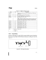
16.1.
ANALOG MODELING
The Pentium Pro processor I/O buffer models are provided to allow simulation of the system lay-
out. Package and socket parasitics for each pin are provided along with the I/O buffer models.
A slow and a fast corner model are provided for both the GTL+ buffer and the CMOS buffer.
The fast model is useful for signal integrity analysis, while the slow model is useful for
maximum flight time calculations. These models are available in IBIS (I/O Buffer Informa-
tion Specification) format from World Wide Web site www.intel.com.
16.2.
IN-TARGET PROBE FOR THE PENTIUM
®
PRO PROCESSOR
(ITP)
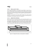
An In-Target Probe (ITP) for the Pentium Pro processor is a debug tool which allows access to
on-chip debug features via a small port on the system board called the debug port. An ITP com-
municates to the Pentium Pro processor through the debug port using a combination of hardware
and software. The software is typically an application running on a host PC. The hardware con-
sists of a board in the host PC connected to the signals which make up the Pentium Pro proces-
sor's debug interface. Due to the nature of an ITP, the Pentium Pro processor may be controlled
without affecting any high speed signals. This ensures that the system can operate at full speed
with an ITP attached. Intel uses an ITP for internal debug and system validation and recom-
mends that all Pentium Pro processor-based system designs include a debug port.
Summary of Contents for Pentium Pro Family
Page 17: ...1 Component Introduction ...
Page 26: ...2 Pentium Pro Processor Architecture Overview ...
Page 27: ......
Page 36: ...3 Bus Overview ...
Page 62: ...4 Bus Protocol ...
Page 105: ...5 Bus Transactions and Operations ...
Page 126: ...6 Range Registers ...
Page 131: ...7 Cache Protocol ...
Page 135: ...8 Data Integrity ...
Page 148: ...9 Configuration ...
Page 161: ...10 Pentium Pro Processor Test Access Port TAP ...
Page 172: ...11 Electrical Specifications ...
Page 201: ...12 GTL Interface Specification ...
Page 229: ...13 3 3V Tolerant Signal Quality Specifications ...
Page 233: ...14 Thermal Specifications ...
Page 239: ...15 Mechanical Specifications ...
Page 241: ...15 2 MECHANICAL SPECIFICATIONS s Figure 15 1 Package Dimensions Bottom View ...
Page 252: ...16 Tools ...
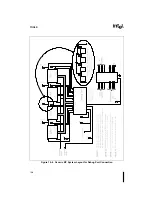
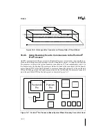
Page 260: ...16 8 TOOLS Figure 16 4 Generic MP System Layout for Debug Port Connection ...
Page 264: ...17 OverDrive Processor Socket Specification ...
Page 290: ...A Signals Reference ...
Page 320: ...Index ...
Page 328: ......