4. SPECIFICATIONS
4-13
4.8 Interface
Specifications
4.8.1 Connector
specifications
This subsection provides the specifications of the interfaces from the Equipment to
external devices. For the insertion positions of each board, see Section 2.1, “External
Views of Operator Access Areas”.
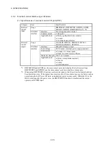
(1) Serial port (COM1)
Pin #
Signal name
Pin #
Signal name
1 CD 6 DSR
2 RD 7 RTS
3 TD 8 CTS
4 DTR 9 RI
5 GND
(2) USB port (front and rear)
Pin #
Signal name
Pin #
Signal name
U1 +5V L1 +5V
U2
USB D0-
L2
USB D1-
U3
USB D0+
L3
USB D1+
U4 GND L4 GND
(3) LAN port (RJ-45 modular jack 8-pin)
Pin #
Signal name
100BASE-TX/10BASE-T 1000BASE-T
1 TX+ TRD0+
2 TX- TRD0-
3 RX+ TRD1+
4 NC TRD2+
5 NC TRD2-
6 RX- TRD1-
7 NC TRD3+
8 NC TRD3-
1
8
5
9
1
6
U1
U2
U3
U4
L1
L2
L3
L4
Summary of Contents for HF-W2000 30
Page 1: ...WIN 62 0060 08 ...
Page 2: ...WIN 62 0060 08 ...
Page 21: ...This Page Intentionally Left Blank ...
Page 29: ...This Page Intentionally Left Blank ...
Page 125: ...This Page Intentionally Left Blank ...
Page 165: ...7 MAINTENANCE ACTIONS 7 32 MEMO ...
Page 189: ...9 RAID1 9 16 MEMO ...
Page 227: ...10 SOFTWARE RAID1 10 38 MEMO ...


