Chapter 3 Parameter
329
Ⅲ
Inst
allation
zero return.
0 0 0 8
***
***
***
DIR5
DIR4 DIRZ
DIRY DIRX
DIRn =1
:
Direction signal (DIR)is high level as each axis moves positively;
=0
:
Direction signal (DIR)is low level as each axis moves negatively.
0 0 0 9
***
***
***
ALM5 ALM4 ALMZ ALMY ALMX
ALMn =1
:
each axis low level alarm signal;
=0
:
each axis high level alarm signal.
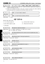
0 0 1 0
CPF7 CPF6 CPF5 CPF4 CPF3 CPF2 CPF1 CPF0
CPF0
~
CPF7
:
Setting values of backlash compensation pulse frequency.
Set frequency =
(
2
7
×CPF7+2
6
×CPF6+2
5
×CPF5+2
4
×CPF4+2
3
×CPF3+2
2
×CPF2+2
1
×CPF1+CPF0
)
Kpps
0 0 1 1
BDEC BD8 ***
***
*** ZNIK
*** ***
BDEC =1
:
Backlash compensation type B, the compensation data are output by ascending type and the
set frequency is invalid.;
=0
:
Backlash compensation type A, the compensation data are output by the set frequency (by bit
parameter No.010) or 1/8 of it.
BD8 =1
:
Backlash compensation is done by the 1/8 of the set frequency;
=0
:
Backlash compensation is done by the set frequency.
ZNIK =1
:
Direction keys locked during zero return, homing continues to end by pressing direction key
once;
=0
:
Direction keys unlocked but should be held on during zero return.
0 0 1 2
***
***
***
G01
*** ***
SOT
ISOT
ISOT =1
:
Prior to machine zero return after power on, manual rapid traverse valid;
=0
:
Prior to machine zero return after power on, manual rapid traverse invalid.
SOT =1
:
Software limit is valid after zero return at power on;
=0
:
Software limit is valid once power on.
G01 =1
:
G01 status when power on;
=0
:
G00 status when power on.
0 0 1 3
CALH ***
***
MZR5 MZR4 MZRZ MZRY MZRX
MZRn =1
:
Machine zero return in negative each axis;
=0
:
Machine zero return in positive each axis.
CALH =1
:
Length offset not cancelled in reference point return;
=0
:
Length offset cancelled in reference point return.
Summary of Contents for 980MDc
Page 19: ...GSK980MDc Milling CNC User Manual XVIII ...
Page 20: ...1 I Programming Programming Ⅰ ...
Page 21: ...GSK980MDc Milling CNC System User Manual 2 I Programming ...
Page 139: ...GSK980MDc Milling CNC System User Manual 120 I Programming ...
Page 191: ...GSK980MDc Milling CNC System User Manual 172 I Programming ...
Page 192: ...173 Ⅱ Operation Ⅱ Operation ...
Page 193: ...GSK980MDc Milling CNC System User Manual 174 Ⅱ Operation ...
Page 200: ...Chapter 1 Operation Mode and Display 181 Ⅱ Operation ...
Page 201: ...GSK980MDc Milling CNC System User Manual 182 Ⅱ Operation ...
Page 249: ...GSK980MDc Milling CNC System User Manual 230 Ⅱ Operation ...
Page 253: ...GSK980MDc Milling CNC System User Manual 234 Ⅱ Operation ...
Page 259: ...GSK980MDc Milling CNC System User Manual 240 Ⅱ Operation ...
Page 265: ...GSK980MDc Milling CNC System User Manual 246 Ⅱ Operation ...
Page 293: ...GSK980MDc Milling CNC System User Manual 274 Ⅱ Operation ...
Page 295: ...GSK980MDc Milling CNC System User Manual 276 Ⅱ Operation ...
Page 319: ...GSK980MDc Milling CNC System User Manual 300 Ⅱ Operation ...
Page 320: ...301 Ⅲ Installation Ⅲ Installation ...
Page 321: ...GSK980MDc Milling CNC System User Manual 302 Ⅲ Installation ...
Page 345: ...GSK980MDc Milling CNC System User Manual 326 Ⅲ Installation ...
Page 391: ...GSK980MDc Milling CNC System User Manual 372 Ⅲ Installation ...
Page 392: ...Appendix 373 Appendix Appendix ...
Page 393: ...GSK980MDc Milling CNC System User Manual 374 Appendix ...
Page 394: ...Appendix 375 Appendix Appendix 1 Outline Dimension of GSK980MDc L N ...


