Chapter 2 Interface Signals
305
Ⅲ
Inst
allation
CHAPTER 2 INTERFACE SIGNALS
2.1 Connection to Drive Unit
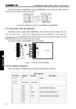
2.1.1 Drive Interface Definition
2.1.2 Command Pulse and Direction Signals
nCP+
,
nCP- are command pulse signals, nDIR+
,
nDIR- are command direction signals. These
two group signals are both difference output
(
AM26LS31
)
, the interior circuit for them is shown in
Fig. 2-2.
Fig. 2-2 Interior circuit of command pulse and direction signals
2.1.3 Drive Unit Alarm Signal
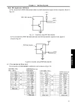
The low or high level of the drive unit alarm level is set by the CNC bit parameter No.009 BIT0
~
BIT4
,
whose interior circuit is shown in Fig. 2-3:
Fig.2-3 interior circuit of drive unit alarm signal
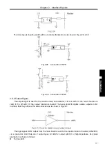
This input circuit requires that the drive unit transmits signal by the following types in Fig. 2-4:
Signal Explanation
CPn+, CPn-
Command pulse signal
DIRn+, DIRn-
Command direction signal
PCn Zero
signal
ALMn
Drive unit alarm signal
ENn
Axis enable signal
SETn
Pulse disable signal
1
:
CPn+
2
:
DIRn+
3
:
PCn
4
:
+24V
5
:
ALMn
6
:
SETn
7
:
ENn
8
:
RDYn/ZSDn
9
:
CPn-
10
:
DIRn-
11
:
GND
12
:
VCC
13
:
VCC
14
:
GND
15
:
GND
Fig.2-1 CN11, CN12, CN13
interface
(
DB15 female
)
ALMn
Summary of Contents for 980MDc
Page 19: ...GSK980MDc Milling CNC User Manual XVIII ...
Page 20: ...1 I Programming Programming Ⅰ ...
Page 21: ...GSK980MDc Milling CNC System User Manual 2 I Programming ...
Page 139: ...GSK980MDc Milling CNC System User Manual 120 I Programming ...
Page 191: ...GSK980MDc Milling CNC System User Manual 172 I Programming ...
Page 192: ...173 Ⅱ Operation Ⅱ Operation ...
Page 193: ...GSK980MDc Milling CNC System User Manual 174 Ⅱ Operation ...
Page 200: ...Chapter 1 Operation Mode and Display 181 Ⅱ Operation ...
Page 201: ...GSK980MDc Milling CNC System User Manual 182 Ⅱ Operation ...
Page 249: ...GSK980MDc Milling CNC System User Manual 230 Ⅱ Operation ...
Page 253: ...GSK980MDc Milling CNC System User Manual 234 Ⅱ Operation ...
Page 259: ...GSK980MDc Milling CNC System User Manual 240 Ⅱ Operation ...
Page 265: ...GSK980MDc Milling CNC System User Manual 246 Ⅱ Operation ...
Page 293: ...GSK980MDc Milling CNC System User Manual 274 Ⅱ Operation ...
Page 295: ...GSK980MDc Milling CNC System User Manual 276 Ⅱ Operation ...
Page 319: ...GSK980MDc Milling CNC System User Manual 300 Ⅱ Operation ...
Page 320: ...301 Ⅲ Installation Ⅲ Installation ...
Page 321: ...GSK980MDc Milling CNC System User Manual 302 Ⅲ Installation ...
Page 345: ...GSK980MDc Milling CNC System User Manual 326 Ⅲ Installation ...
Page 391: ...GSK980MDc Milling CNC System User Manual 372 Ⅲ Installation ...
Page 392: ...Appendix 373 Appendix Appendix ...
Page 393: ...GSK980MDc Milling CNC System User Manual 374 Appendix ...
Page 394: ...Appendix 375 Appendix Appendix 1 Outline Dimension of GSK980MDc L N ...


