GSK980MDc Milling CNC User Manual
XIV
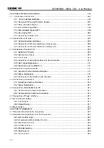
CHAPTER 2 INTERFACE SIGNALS............................................................................................. 305
2.1 Connection to Drive Unit ....................................................................................................... 305
2.1.1 Drive Interface Definition ............................................................................................ 305
2.1.2 Command Pulse and Direction Signals ......................................................................... 305
2.1.3 Drive Unit Alarm Signal ................................................................................................. 305
2.1.4 Axis Enable Signal ENn................................................................................................. 306
2.1.5 Pulse Disable Signal SETn ........................................................................................... 306
2.1.6 Zero Signal nPC ............................................................................................................ 306
2.1.7 Connection to Drive Unit ............................................................................................... 307
2.2 Connection of 4th Axis............................................................................................................. 308
2.2.1 4th Axis Interface Definition ........................................................................................... 308
2.2.2 Connection of 4th Axis Interface as Linear Axis............................................................. 308
2.2.3 Connection of 4th Axis Interface as Rotary Axis ............................................................ 309
2.3 Connection of Spindle Port ...................................................................................................... 309
2.3.1 Definition of Signal ........................................................................................................ 309
2.3.2 Spindle Zero Signal ....................................................................................................... 310
2.3.3 Linear Axis..................................................................................................................... 310
2.3.4 Connection of Spindle interface and Servo Spindle....................................................... 310
2.3.5 SVC Signal Explanation ................................................................................................ 311
2.3.6 Explanations for ALM5(X5.3)......................................................................................... 311
2.4 Connection to Spindle Encoder ............................................................................................... 311
2.4.1 Spindle Encoder Interface Definition ............................................................................. 311
2.4.2 Signal Explanation......................................................................................................... 311
2.4.3 Connection of Spindle Encoder Interface ...................................................................... 312
2.5 Connection to Handwheel ....................................................................................................... 312
2.5.1Handwheel Interface Definition....................................................................................... 312
2.5.2 Signal Explanation......................................................................................................... 313
2.6 Connection of GSK980MDc to PC .......................................................................................... 313
2.6.1 Communication Interface Definition............................................................................... 313
2.6.2 Communication Interface Connection ........................................................................... 313
2.7 Connection of Power Interface ................................................................................................ 314
2.8 I/O Interface Definition
:
......................................................................................................... 314
2.8.1 Input Signal ................................................................................................................... 316
2.8.2 Output Signal................................................................................................................. 317
2.9 Machine Zero .......................................................................................................................... 318
CHAPTER 3 PARAMETER ........................................................................................................... 327
3.1 Parameter Description (by Sequence)..................................................................................... 327
3.2 Parameter Description (by Function Sequence) ...................................................................... 343
3.2.1 Axis Control Logic.......................................................................................................... 343
3.2.2 Acceleration & Deceleration Control.............................................................................. 345
3.2.3 Machine Protection........................................................................................................ 346
3.2.4 Thread Function ............................................................................................................ 346
3.2.5 Encoder tapping ............................................................................................................ 349
3.2.6 Rigid tapping ................................................................................................................. 349
3.2.7 Tool Function ................................................................................................................. 350
Summary of Contents for 980MDc
Page 19: ...GSK980MDc Milling CNC User Manual XVIII ...
Page 20: ...1 I Programming Programming Ⅰ ...
Page 21: ...GSK980MDc Milling CNC System User Manual 2 I Programming ...
Page 139: ...GSK980MDc Milling CNC System User Manual 120 I Programming ...
Page 191: ...GSK980MDc Milling CNC System User Manual 172 I Programming ...
Page 192: ...173 Ⅱ Operation Ⅱ Operation ...
Page 193: ...GSK980MDc Milling CNC System User Manual 174 Ⅱ Operation ...
Page 200: ...Chapter 1 Operation Mode and Display 181 Ⅱ Operation ...
Page 201: ...GSK980MDc Milling CNC System User Manual 182 Ⅱ Operation ...
Page 249: ...GSK980MDc Milling CNC System User Manual 230 Ⅱ Operation ...
Page 253: ...GSK980MDc Milling CNC System User Manual 234 Ⅱ Operation ...
Page 259: ...GSK980MDc Milling CNC System User Manual 240 Ⅱ Operation ...
Page 265: ...GSK980MDc Milling CNC System User Manual 246 Ⅱ Operation ...
Page 293: ...GSK980MDc Milling CNC System User Manual 274 Ⅱ Operation ...
Page 295: ...GSK980MDc Milling CNC System User Manual 276 Ⅱ Operation ...
Page 319: ...GSK980MDc Milling CNC System User Manual 300 Ⅱ Operation ...
Page 320: ...301 Ⅲ Installation Ⅲ Installation ...
Page 321: ...GSK980MDc Milling CNC System User Manual 302 Ⅲ Installation ...
Page 345: ...GSK980MDc Milling CNC System User Manual 326 Ⅲ Installation ...
Page 391: ...GSK980MDc Milling CNC System User Manual 372 Ⅲ Installation ...
Page 392: ...Appendix 373 Appendix Appendix ...
Page 393: ...GSK980MDc Milling CNC System User Manual 374 Appendix ...
Page 394: ...Appendix 375 Appendix Appendix 1 Outline Dimension of GSK980MDc L N ...


