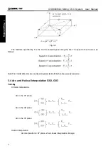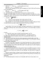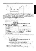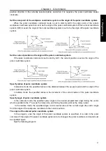
Chapter 3 G Command
45
I Programming
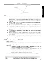
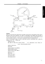
N1 G17 G54 G90 G16; ……Specify the polar coordinate command and select XY plane. Set the zero
point of the workpiece coordinate system G54 as the origin of the polar
coordinate command
N2 G81 X100 Y30 Z-20 R-5 F200; ……Specify a distance of 100mm and an angle of 30 degrees
N3 Y150; ……Specify a distance of 100mm and an angle of 150 degrees
N4 Y270; ……Specify a distance of 100mm and an angle of 270 degrees
N5 G15 G80; ……Cancel the polar coordinate system command
z
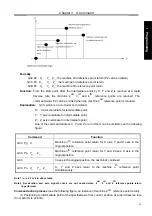
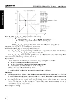
Specify angles with relative values
N1 G17 G54 G90 G16;
……Specify the polar coordinate command and select XY plane. Set the zero
point of the workpiece coordinate system G54 as the origin of the polar coordinate command.
N2 G81 X100 Y30 Z-20 R-5 F200;
……Specify a distance of 100mm and an angle of 30 degrees
N3 G91 Y120;
……Specify a distance of 100mm and an angle of +120 degrees
N4 Y120;
……Specify a distance of 100mm and an angle of +120 degrees
N5 G15 G80;
……Cancel the polar coordinate system command
3.9 Plane Selection Command G17, G18 and G19
Format
:
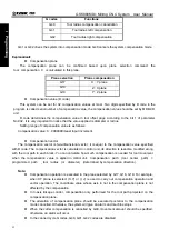
G17
……XY
plane
G18
……ZX
plane
G19
……YZ
plane
Function
:
The plane of arc interpolation and tool radius compensation are chosen by using the G code.
Explanation
:
G17, G18 and G19 are modal G commands, the plane will not be changed
when a block without any command inside.
Command example
:
G18
X_
Z_
;
ZX plane
X_ Y_
;
Invariable plane (ZX plane)
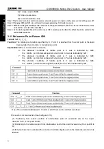
Note 1: The plane selection command can share the same block with other group G commands.
Note 2: The move command is regardless of the plane selection. For example, the Z axis is not
On XY plane, the Z
axis movement is regardless of the XY plane in command G17 Z_ .
3.10 Conversion of Inch and Metric G20 and G21
Format
:
G20/G21
;
Function:
The input unit either inch or metric is chosen by G code.
Explanation
:
Unit system
G codes
least setting unit
Metric G20
0.0001
inch
Inch G21
0.001
mm
The G code should be placed in front of the program when inch and metric is switched each other.
Before the coordinate system is set, it is specified by a single block command.
The following unit systems vary according to the G code for inch or metric conversion.
(1) Feedrate command value by F.
(2) Command value related to the position.
(3) Offset.
Summary of Contents for 980MDc
Page 19: ...GSK980MDc Milling CNC User Manual XVIII ...
Page 20: ...1 I Programming Programming Ⅰ ...
Page 21: ...GSK980MDc Milling CNC System User Manual 2 I Programming ...
Page 139: ...GSK980MDc Milling CNC System User Manual 120 I Programming ...
Page 191: ...GSK980MDc Milling CNC System User Manual 172 I Programming ...
Page 192: ...173 Ⅱ Operation Ⅱ Operation ...
Page 193: ...GSK980MDc Milling CNC System User Manual 174 Ⅱ Operation ...
Page 200: ...Chapter 1 Operation Mode and Display 181 Ⅱ Operation ...
Page 201: ...GSK980MDc Milling CNC System User Manual 182 Ⅱ Operation ...
Page 249: ...GSK980MDc Milling CNC System User Manual 230 Ⅱ Operation ...
Page 253: ...GSK980MDc Milling CNC System User Manual 234 Ⅱ Operation ...
Page 259: ...GSK980MDc Milling CNC System User Manual 240 Ⅱ Operation ...
Page 265: ...GSK980MDc Milling CNC System User Manual 246 Ⅱ Operation ...
Page 293: ...GSK980MDc Milling CNC System User Manual 274 Ⅱ Operation ...
Page 295: ...GSK980MDc Milling CNC System User Manual 276 Ⅱ Operation ...
Page 319: ...GSK980MDc Milling CNC System User Manual 300 Ⅱ Operation ...
Page 320: ...301 Ⅲ Installation Ⅲ Installation ...
Page 321: ...GSK980MDc Milling CNC System User Manual 302 Ⅲ Installation ...
Page 345: ...GSK980MDc Milling CNC System User Manual 326 Ⅲ Installation ...
Page 391: ...GSK980MDc Milling CNC System User Manual 372 Ⅲ Installation ...
Page 392: ...Appendix 373 Appendix Appendix ...
Page 393: ...GSK980MDc Milling CNC System User Manual 374 Appendix ...
Page 394: ...Appendix 375 Appendix Appendix 1 Outline Dimension of GSK980MDc L N ...


