Chapter 2 Interface Signals
319
Ⅲ
Inst
allation
DECZ
Z axis deceleration signal
PCZ
Z axis zero signal
DEC4
4
th
axis deceleration signal
PC4
4
th
axis zero signal
DEC5
5
th
axis deceleration signal
PC5
5
th
axis zero signal
z
CNC
diagnosis
0 0 0
DEC5
DEC4 DECZ DECY
DECX
Corresponding
pin-out
CN61.34
CN61.33
CN61.12 CN61.32
CN61.4
PLC address
X2.5
X2.4
X1.3
X2.3
X0.3
0 0 8
PC5 PC4 PCZ
PCY
PCX
Corresponding
pin-out
CN15.10 CN14.3 CN13.3 CN12.3
CN11.3
z
Bit
parameter
0 0 6
ZM5
ZM4
ZMZ
ZMY
ZMX
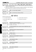
ZMn =1
:
n axis machine zero return type C;
=0
:
n axis machine zero return type B.
n: X, Y, Z, 4, 5
0 0 7
ZC4
ZCZ
ZCY
ZCX
ZCn =1
:
The deceleration signal
(
DECn
)
and one-rotation signal
(
PCn
)
of X axis are in parallel
connection during machine zero return ( a proximity switch acting as both the deceleration
signal and zero signal );
=0
:
The deceleration signal
(
DECn
)
and one-rotation signal
(
PCn
)
of X axis are connected
independently during machine zero return
(
the indepent deceleration signal and zero signal are
required
)
.
n: X, Y, Z, 4 th
0 0 1 1
ZNIK
ZNLK =1
:
The direction keys are locked as machine zero return is performed, by pressing the direction
key once, it moves to the machine zero automatically and stops, By pressing the
key at
the machine zero return, the motion stops immediately;
=0
:
The direction keys are not locked as machine zero return is performed, but the direction keys
should be pressed and held on
0 0 1 2
ISOT
ISOT =1
:
Manual rapid traverse valid prior to machine zero return;
=0
:
Manual rapid traverse invalid prior to machine zero return.
0
0 1 4
ZRS5
ZRS4
ZRSZ
ZRSY
ZRSX
ZRSZ, ZRSX, ZRSY, ZRS4, ZRS5 =1: To select machine zero return type B, C, which have
machine zero, it needs to detect deceleration and zero signals in machine zero return;
Summary of Contents for 980MDc
Page 19: ...GSK980MDc Milling CNC User Manual XVIII ...
Page 20: ...1 I Programming Programming Ⅰ ...
Page 21: ...GSK980MDc Milling CNC System User Manual 2 I Programming ...
Page 139: ...GSK980MDc Milling CNC System User Manual 120 I Programming ...
Page 191: ...GSK980MDc Milling CNC System User Manual 172 I Programming ...
Page 192: ...173 Ⅱ Operation Ⅱ Operation ...
Page 193: ...GSK980MDc Milling CNC System User Manual 174 Ⅱ Operation ...
Page 200: ...Chapter 1 Operation Mode and Display 181 Ⅱ Operation ...
Page 201: ...GSK980MDc Milling CNC System User Manual 182 Ⅱ Operation ...
Page 249: ...GSK980MDc Milling CNC System User Manual 230 Ⅱ Operation ...
Page 253: ...GSK980MDc Milling CNC System User Manual 234 Ⅱ Operation ...
Page 259: ...GSK980MDc Milling CNC System User Manual 240 Ⅱ Operation ...
Page 265: ...GSK980MDc Milling CNC System User Manual 246 Ⅱ Operation ...
Page 293: ...GSK980MDc Milling CNC System User Manual 274 Ⅱ Operation ...
Page 295: ...GSK980MDc Milling CNC System User Manual 276 Ⅱ Operation ...
Page 319: ...GSK980MDc Milling CNC System User Manual 300 Ⅱ Operation ...
Page 320: ...301 Ⅲ Installation Ⅲ Installation ...
Page 321: ...GSK980MDc Milling CNC System User Manual 302 Ⅲ Installation ...
Page 345: ...GSK980MDc Milling CNC System User Manual 326 Ⅲ Installation ...
Page 391: ...GSK980MDc Milling CNC System User Manual 372 Ⅲ Installation ...
Page 392: ...Appendix 373 Appendix Appendix ...
Page 393: ...GSK980MDc Milling CNC System User Manual 374 Appendix ...
Page 394: ...Appendix 375 Appendix Appendix 1 Outline Dimension of GSK980MDc L N ...


