Appendix
411
Appendix
S instruction has appointed.
●
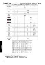
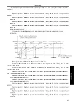
Signal Address:
G33
SIND
G35
SIND2
S 12-bit code input signal R01I
~
R12I(G32.0~G33.3)
2
nd
spindle S 12-bit code input signal R01I2
~
R12I2(G34.0~G35.3)
●
Signal Type: PLC
→
NC
●
Signal Function: PLC issues speed instruction value that inputs spindle motor. Spindle motor speed
is appointed in the form of binary code value from 0 to 4095.
●
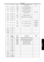
Signal Address:
G32
R08I
R07I
R06I
R05I
R04I R03I R02I R01I
G33
R12I R11I R10I R09I
G34
R08I2
R07I2
R06I2
R05I2
R04I2
R03I2 R02I2 R01I2
G35
R12I2
R11I2 R10I2 R09I2
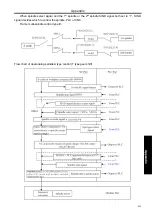
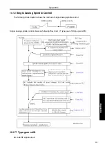
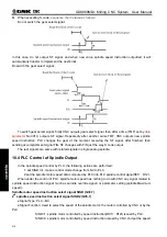
10.5 Spindle Orientation Function
Spindle orientation signal (SOR) G29.5
When this signal is '1', spindle stops; while is '0', spindle is spinning in a certain speed set by data
parameter
(No.3732)
. No matter how is the gear state, spindle will rotate at a certain speed, so in the
mechanical spindle positioning, it can be used to rotate into the brake and pin and so on.
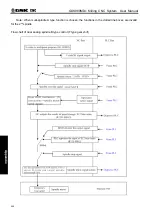
In M series, spindle motor can be made rotating in a certain speed by setting data parameter NO.3732,
in which situation because the rotating speed is constant in the gear switch devices, it can be used to
gear shift.When spindle stop signal SSTP is 1, spindle orientation signal SOR is invalid.
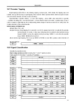
When bit parameter GST is 0, SOR signal is used for spindle orientation, of which speed is decided by
data parameter3732, while gear stage select signal does not change. For instance, if at the, SOR signal
turns to 1, while the speed data parameter 3732 set is not in the range of the low speed gear, due to
gear-stage signal is not alter, CNC will compute the corresponding speed still according to high speed gear
curve.When bit parameter GST is 1 SOR signal is used for control the motor speed. The output instruction
has no connection with gear-stage, set suitable spindle motor speed to control gear shift.
Summary of Contents for 980MDc
Page 19: ...GSK980MDc Milling CNC User Manual XVIII ...
Page 20: ...1 I Programming Programming Ⅰ ...
Page 21: ...GSK980MDc Milling CNC System User Manual 2 I Programming ...
Page 139: ...GSK980MDc Milling CNC System User Manual 120 I Programming ...
Page 191: ...GSK980MDc Milling CNC System User Manual 172 I Programming ...
Page 192: ...173 Ⅱ Operation Ⅱ Operation ...
Page 193: ...GSK980MDc Milling CNC System User Manual 174 Ⅱ Operation ...
Page 200: ...Chapter 1 Operation Mode and Display 181 Ⅱ Operation ...
Page 201: ...GSK980MDc Milling CNC System User Manual 182 Ⅱ Operation ...
Page 249: ...GSK980MDc Milling CNC System User Manual 230 Ⅱ Operation ...
Page 253: ...GSK980MDc Milling CNC System User Manual 234 Ⅱ Operation ...
Page 259: ...GSK980MDc Milling CNC System User Manual 240 Ⅱ Operation ...
Page 265: ...GSK980MDc Milling CNC System User Manual 246 Ⅱ Operation ...
Page 293: ...GSK980MDc Milling CNC System User Manual 274 Ⅱ Operation ...
Page 295: ...GSK980MDc Milling CNC System User Manual 276 Ⅱ Operation ...
Page 319: ...GSK980MDc Milling CNC System User Manual 300 Ⅱ Operation ...
Page 320: ...301 Ⅲ Installation Ⅲ Installation ...
Page 321: ...GSK980MDc Milling CNC System User Manual 302 Ⅲ Installation ...
Page 345: ...GSK980MDc Milling CNC System User Manual 326 Ⅲ Installation ...
Page 391: ...GSK980MDc Milling CNC System User Manual 372 Ⅲ Installation ...
Page 392: ...Appendix 373 Appendix Appendix ...
Page 393: ...GSK980MDc Milling CNC System User Manual 374 Appendix ...
Page 394: ...Appendix 375 Appendix Appendix 1 Outline Dimension of GSK980MDc L N ...


