Chapter 3 Parameter
335
Ⅲ
Inst
allation
=0
:
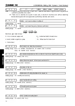
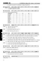
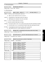
Plane returning is selected by G99 in continuous drilling
0 5 8 4
***
***
***
***
*** ***
RD2 RD1
RD2 =1
:
Retraction in Y axis direction of G76, G87
;
=0
:
Retraction in X axis direction of G76, G87
;
RD1 =1
:
Retraction in Y axis direction of G76, G87
;
=0
:
Retraction in X axis direction of G76, G87.
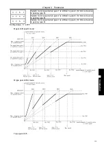
0 5 8 8
RTORI RHD5 RTPCP ***
*** RTCRG RTCRS
***
RTORI =1
:
M29 is executed, Spindle need to return zero;
=0
:
M29 is executed, Spindle need not to return zero.
RTPCP =1
:
Rigid tapping is the high-speed deep hole cycle(G73);
=0
:
Rigid tapping is the high-speed deep hole cycle (G83).
RHD5 =1
:
5th axis coordinate information is hided
;
=0
:
5th axis coordinate information isn’t hided
RTCRG=1
:
Do not wait for G61.0 to be 1 as executing next program block after rigid tapping cancelled;
=0
:
Do wait for G61.0 to be 1 as executing next program block after rigid tapping cancelled.
RTCRS=1
:
Rigid tapping proportion of gear setting by CNC automatically;
=0: Rigid tapping proportion of gear setting by CNC parameter.
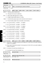
0 6 0 0
***
***
***
***
*** GST
GTT SGB
SGB
=1: M-type gear shift mode B
;
=0
:
M-type gear shift mode A.
GST =1
:
Analog spindle gear shit is M;
=0
:
Analog spindle gear shit is T.
GST =1
:
Positioning signal is used for gear shift;
=0
:
Positioning signal is used for spindle orientation.
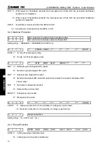
0 6 0 1
MSI ***
MSEN ***
*** ***
*** ***
MSI =1: Multi-Spindle control function is B type
;
=0: Multi-Spindle control function is A type.
MSEN =1: Multi-Spindle function is valid
;
=0: Multi-Spindle function is invalid.
0
6
5
0
*** *** *** *** *** *** PRPD
PLA
PLA =1
:
PLC axis control is valid;
=0
:
PLC axis control is invalid.
PRPD =1
:
PLC axis rapidly uses input value;
=0
:
PLC axis rapidly uses input parameter.
0 7 0 0
***
***
***
***
*** ***
*** CHPW
CHPW =1
:
Real-time detection for the stability of voltage isn’t performed
;
Summary of Contents for 980MDc
Page 19: ...GSK980MDc Milling CNC User Manual XVIII ...
Page 20: ...1 I Programming Programming Ⅰ ...
Page 21: ...GSK980MDc Milling CNC System User Manual 2 I Programming ...
Page 139: ...GSK980MDc Milling CNC System User Manual 120 I Programming ...
Page 191: ...GSK980MDc Milling CNC System User Manual 172 I Programming ...
Page 192: ...173 Ⅱ Operation Ⅱ Operation ...
Page 193: ...GSK980MDc Milling CNC System User Manual 174 Ⅱ Operation ...
Page 200: ...Chapter 1 Operation Mode and Display 181 Ⅱ Operation ...
Page 201: ...GSK980MDc Milling CNC System User Manual 182 Ⅱ Operation ...
Page 249: ...GSK980MDc Milling CNC System User Manual 230 Ⅱ Operation ...
Page 253: ...GSK980MDc Milling CNC System User Manual 234 Ⅱ Operation ...
Page 259: ...GSK980MDc Milling CNC System User Manual 240 Ⅱ Operation ...
Page 265: ...GSK980MDc Milling CNC System User Manual 246 Ⅱ Operation ...
Page 293: ...GSK980MDc Milling CNC System User Manual 274 Ⅱ Operation ...
Page 295: ...GSK980MDc Milling CNC System User Manual 276 Ⅱ Operation ...
Page 319: ...GSK980MDc Milling CNC System User Manual 300 Ⅱ Operation ...
Page 320: ...301 Ⅲ Installation Ⅲ Installation ...
Page 321: ...GSK980MDc Milling CNC System User Manual 302 Ⅲ Installation ...
Page 345: ...GSK980MDc Milling CNC System User Manual 326 Ⅲ Installation ...
Page 391: ...GSK980MDc Milling CNC System User Manual 372 Ⅲ Installation ...
Page 392: ...Appendix 373 Appendix Appendix ...
Page 393: ...GSK980MDc Milling CNC System User Manual 374 Appendix ...
Page 394: ...Appendix 375 Appendix Appendix 1 Outline Dimension of GSK980MDc L N ...

