Chapter 3 G Command
55
I Programming
Compensation axes can be regarded as Z, Y and X. Either absolute or
incremental command, the end point coordinate value specified by Z axis movement command in
program adds the offset specified by H codes in G43 (set in the offset storage), or subtracts the offset
specified by H code in G44, finally, the value calculated is regarded as the end point coordinate.
The following command is indicated for Z axis move omitting: When the offset is positive, G43 is for an
offset in the positive direction; G44 is for an offset in the negative direction.
It reversely moves when the offset is negative value.
Specifying the offset
An offset number is specified by H code and its corresponding offset adds or
subtracts Z axis movement command value in program to get a new Z axis movement command value.
The offset number is H00~H32.
Offset value corresponded with offset number is pre-set in the offset storage by using the panel of
LCD/MDI. Setting range for offset is as follows:
Offset value: -9999999
~
9999999×least input increment
Offset number 00, i.e. H00 corresponds to the 0 offset. It is disabled to set offset value to H00.
Tool length compensation cancellation
G49 or H00 can be specified when the tool length compensation is cancelled. When two or more
axes compensations are cancelled, all of the axes compensation will be cancelled if the G49 is applied.
Compensation value of the vertical axis for currently specified plane is cancelled with H00. After G49 or
H00 is specified, the system immediately cancels the compensation value.
Note 1: In the block that tool length compensation is specified, G02
,
G03, G04, G92
,
G31
,
G142 and G143 cannot be
specified at the same time, otherwise, an alarm will occur.
Note 2:Tool length compensation command can be specified in the block in which canned cycle is specified. But
after the canned cycle is executed, the tool length compensation is disabled and is not modal.
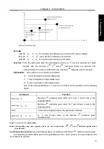
Example
:
Normal
Modal Explanation (H1=10.0mm
,
H2=20.0mm)
G43 H1
G44 G01 X50 Y50 Z50 H2
G90 G00 X100 Y100 Z100
G43 H1
G44 H2
G44 H2
Setting H1, tool length compensation in the positive
direction.
Linear interpolation, setting H2 tool length
compensation in negative direction
Position to X100 Y100 Z100(Z80) with H2
compensation offset.
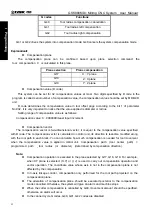
In the same block with G02,G03,G04,G31,G92
G43 H1
G49 G02 X50 R25 H2
G43 H1
G43 H1
Setting H1 tool length compensation in the positive
direction.
Alarm occurs.
In the same block with canned cycle code
G43 H1
G44 G81 X50 R5 Z-70 H2
G90 G00 X100 Y100 Z100
G43 H1
G44 H2
G44 H2
Setting H1 tool length compensation in the positive
direction.
Setting H2 tool length compensation in the negative
direction. Starts the canned cycle from H2.
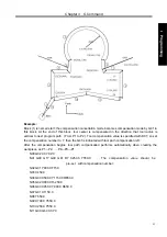
Specified in the canned cycle
G43 H1
G90 G81 X50 R5 Z-70
G49 H2
G49 G0 X75 Y75 Z75 H0
G43 H1
G43 H1
G43 H1
G49 H0
Setting H1 tool length compensation in the positive
direction.
Compensation offset with H1; enters into canned
cycle mode.
The tool length compensation (G49,H2) in the canned
Summary of Contents for 980MDc
Page 19: ...GSK980MDc Milling CNC User Manual XVIII ...
Page 20: ...1 I Programming Programming Ⅰ ...
Page 21: ...GSK980MDc Milling CNC System User Manual 2 I Programming ...
Page 139: ...GSK980MDc Milling CNC System User Manual 120 I Programming ...
Page 191: ...GSK980MDc Milling CNC System User Manual 172 I Programming ...
Page 192: ...173 Ⅱ Operation Ⅱ Operation ...
Page 193: ...GSK980MDc Milling CNC System User Manual 174 Ⅱ Operation ...
Page 200: ...Chapter 1 Operation Mode and Display 181 Ⅱ Operation ...
Page 201: ...GSK980MDc Milling CNC System User Manual 182 Ⅱ Operation ...
Page 249: ...GSK980MDc Milling CNC System User Manual 230 Ⅱ Operation ...
Page 253: ...GSK980MDc Milling CNC System User Manual 234 Ⅱ Operation ...
Page 259: ...GSK980MDc Milling CNC System User Manual 240 Ⅱ Operation ...
Page 265: ...GSK980MDc Milling CNC System User Manual 246 Ⅱ Operation ...
Page 293: ...GSK980MDc Milling CNC System User Manual 274 Ⅱ Operation ...
Page 295: ...GSK980MDc Milling CNC System User Manual 276 Ⅱ Operation ...
Page 319: ...GSK980MDc Milling CNC System User Manual 300 Ⅱ Operation ...
Page 320: ...301 Ⅲ Installation Ⅲ Installation ...
Page 321: ...GSK980MDc Milling CNC System User Manual 302 Ⅲ Installation ...
Page 345: ...GSK980MDc Milling CNC System User Manual 326 Ⅲ Installation ...
Page 391: ...GSK980MDc Milling CNC System User Manual 372 Ⅲ Installation ...
Page 392: ...Appendix 373 Appendix Appendix ...
Page 393: ...GSK980MDc Milling CNC System User Manual 374 Appendix ...
Page 394: ...Appendix 375 Appendix Appendix 1 Outline Dimension of GSK980MDc L N ...

