Appendix
387
Appendix
7.2 Setting of Spindle Electronic Gear Ratio
Calculation formula of CNC:
D
M
Z
Z
CMD
CMR
×
=
α
δ
CMR
CMD
Z
Z
D
M
×
×
=
δ
α
CMR: Multiplier coefficient of spindle command
CMD: Frequency division coefficient of spindle command
α
: Pulse volume, motor rotation angle for a pulse
δ
: Min. input command unit of CNC (0.001°, 0.01° or 0.0001°), this value corresponds to the travel
amount of a revolution of the spindle (related parameters 5216). When 5216 is set to 1000,
δ
=360/1000=0.360
°
ZM: Gear teeth of lead screw
ZD: Gear teeth of motor
Calculation formula of spindle servo drive unit:
Parameter 12, 13 of drive unit correspond to the pulse frequency division numerator of position
command respectively. The calculation formulas for pulse frequency division denominator of position
command and gear ratio of drive unit are as follows:
C
N
G
P
×
×
=
×
4
And:
CMR
CMD
Z
Z
C
C
N
P
C
N
G
D
M
×
×
×
×
=
×
×
×
=
×
×
=
δ
α
360
4
360
4
4
P: Correspondence between required pulse amounts for motor rotates 360 degrees and CNC end:
α
/
360
=
P
G: Electronic gear ratio of drive unit, G= position command pulse frequency division numerator/
position command pulse frequency division denominator
N: Set motor rev number to 1
C: Wire number of feedback encoder
In order to enhance the machining accuracy, the gear ratio of spindle servo drive is usually set to 1:1,
namely, G=1 in the above formula, and the evolving process is as follows:
1
360
4
=
×
×
×
×
CMR
CMD
Z
Z
C
D
M
δ
D
M
Z
Z
C
CMD
CMR
×
×
×
=
δ
360
4
In order to match with DAP03, C=1024, spindle connects to the motor, Z
M
/Z
D
=1, and it is suggested
that the data parameter 5216 of CNC is set to 1000 (Now the incremental system of the 5
th
axis is 0.001°)
Summary of Contents for 980MDc
Page 19: ...GSK980MDc Milling CNC User Manual XVIII ...
Page 20: ...1 I Programming Programming Ⅰ ...
Page 21: ...GSK980MDc Milling CNC System User Manual 2 I Programming ...
Page 139: ...GSK980MDc Milling CNC System User Manual 120 I Programming ...
Page 191: ...GSK980MDc Milling CNC System User Manual 172 I Programming ...
Page 192: ...173 Ⅱ Operation Ⅱ Operation ...
Page 193: ...GSK980MDc Milling CNC System User Manual 174 Ⅱ Operation ...
Page 200: ...Chapter 1 Operation Mode and Display 181 Ⅱ Operation ...
Page 201: ...GSK980MDc Milling CNC System User Manual 182 Ⅱ Operation ...
Page 249: ...GSK980MDc Milling CNC System User Manual 230 Ⅱ Operation ...
Page 253: ...GSK980MDc Milling CNC System User Manual 234 Ⅱ Operation ...
Page 259: ...GSK980MDc Milling CNC System User Manual 240 Ⅱ Operation ...
Page 265: ...GSK980MDc Milling CNC System User Manual 246 Ⅱ Operation ...
Page 293: ...GSK980MDc Milling CNC System User Manual 274 Ⅱ Operation ...
Page 295: ...GSK980MDc Milling CNC System User Manual 276 Ⅱ Operation ...
Page 319: ...GSK980MDc Milling CNC System User Manual 300 Ⅱ Operation ...
Page 320: ...301 Ⅲ Installation Ⅲ Installation ...
Page 321: ...GSK980MDc Milling CNC System User Manual 302 Ⅲ Installation ...
Page 345: ...GSK980MDc Milling CNC System User Manual 326 Ⅲ Installation ...
Page 391: ...GSK980MDc Milling CNC System User Manual 372 Ⅲ Installation ...
Page 392: ...Appendix 373 Appendix Appendix ...
Page 393: ...GSK980MDc Milling CNC System User Manual 374 Appendix ...
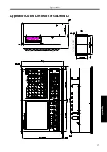
Page 394: ...Appendix 375 Appendix Appendix 1 Outline Dimension of GSK980MDc L N ...

