Chapter 6 Screw-Pitch Compensation
367
Ⅲ
Inst
allation
CHAPTER 6 SCREW-PITCH COMPENSATION
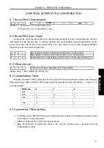
6.1 Screw-Pitch Compensation
0
0 0 3
***
***
PCOMP
*** ***
*** D/R
***
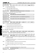
PCOMP =1: Screw-pitch error compensation valid;
=0: Screw-pitch error compensation invalid.
6.2 Screw-Pitch Error Origin
A position No. which the screw-pitch error compensation starts from in the compensation list, which is
determined from the machine zero, is called screw-pitch error compensation origin (compensation original
point). Each axis may be set in any position from 0 to 1023, which is set by data parameter
№
3620
depending on the mechanical requirement.
3
6 2
1
Min. position number of each axis for pitch error compensation
3
6 2
2
Max. position number of each axis for pitch error compensation
3
6 2
0
Screw-pitch error compensation position number of each axis machine zero
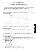
6.3 Offset Interval
3
6 2
4
Interval of each axis screw-pitch error compensation
Setting range
:
1000
~
999999 (Unit:0.001mm)
6.4 Compensation Value
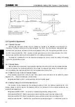
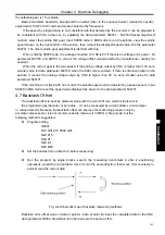
The axes screw-pitch offset values are set in the page of screw-pitch parameter. Refer to the following
table. Input range: -2550~2550.The offset value is input by diameter with the unit 0.001mm.
(
Take X, Y, Z
axes as example
)
Offset No.
X
Y
Z
000 …
…
…
001 5
-2
3
002 -3
4
-1
… …
…
…
199 -2
3
1
… …
…
…
6.5 Cautions for Offset Setting
①
The setting and modification of screw-pitch offset can only be done at the authority of password level
2 and switch on parameter switch.
②
Offset is not allowed if the offset interval entered is 0
③
After the parameter of screw-pitch offset is set, only the machine zero is returned could the
compensation be done.
Summary of Contents for 980MDc
Page 19: ...GSK980MDc Milling CNC User Manual XVIII ...
Page 20: ...1 I Programming Programming Ⅰ ...
Page 21: ...GSK980MDc Milling CNC System User Manual 2 I Programming ...
Page 139: ...GSK980MDc Milling CNC System User Manual 120 I Programming ...
Page 191: ...GSK980MDc Milling CNC System User Manual 172 I Programming ...
Page 192: ...173 Ⅱ Operation Ⅱ Operation ...
Page 193: ...GSK980MDc Milling CNC System User Manual 174 Ⅱ Operation ...
Page 200: ...Chapter 1 Operation Mode and Display 181 Ⅱ Operation ...
Page 201: ...GSK980MDc Milling CNC System User Manual 182 Ⅱ Operation ...
Page 249: ...GSK980MDc Milling CNC System User Manual 230 Ⅱ Operation ...
Page 253: ...GSK980MDc Milling CNC System User Manual 234 Ⅱ Operation ...
Page 259: ...GSK980MDc Milling CNC System User Manual 240 Ⅱ Operation ...
Page 265: ...GSK980MDc Milling CNC System User Manual 246 Ⅱ Operation ...
Page 293: ...GSK980MDc Milling CNC System User Manual 274 Ⅱ Operation ...
Page 295: ...GSK980MDc Milling CNC System User Manual 276 Ⅱ Operation ...
Page 319: ...GSK980MDc Milling CNC System User Manual 300 Ⅱ Operation ...
Page 320: ...301 Ⅲ Installation Ⅲ Installation ...
Page 321: ...GSK980MDc Milling CNC System User Manual 302 Ⅲ Installation ...
Page 345: ...GSK980MDc Milling CNC System User Manual 326 Ⅲ Installation ...
Page 391: ...GSK980MDc Milling CNC System User Manual 372 Ⅲ Installation ...
Page 392: ...Appendix 373 Appendix Appendix ...
Page 393: ...GSK980MDc Milling CNC System User Manual 374 Appendix ...
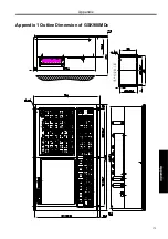
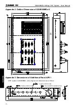
Page 394: ...Appendix 375 Appendix Appendix 1 Outline Dimension of GSK980MDc L N ...


