Chapter 4 Control Function of Additional Axis
127
I Programming
The zero return of Cs axis is performed opening the feed axis and the direction selection
signal
+
Jn (G100) or
-
Jn (G102).
z
Automatic
Specify G28 after the spindle enters the Cs contour control mode, and the spindle moves to
the intermediate point and then return to the reference position.
ZPn (F094) becomes 1 after the reference position return is executed.
The operation of Cs contour control axis
(Manual/Automatic)
If the Cs contour control axis has been returned to the reference position, the operation of Cs
axis is same as the common NC axis.
In the spindle speed control, the Cs contour control axis can not be performed. Otherwise, the
system alarms.
So, in the spindle speed control mode, it is not permitted the manual operation of Cs by the
PLC ladder diagram.
The signal shift of spindle contour control
CON (G027#7)
[Type] Signal input
[Function] This signal is used for shifting between spindle speed control mode and
Cs contour control mode.
When this signal is set to 1, the spindle is shifted to the Cs contour control mode from
speed control mode.
When this signal is set to 0, the Cs contour control mode comes back to the speed
control mode.
The signal shift end of spindle contour control
FSCSL(F044#1)
[Type] Signal output
[Function] This signal indicates that the controlled axis has been controlled under the
Cs contour.
[Output condition] Spindle speed control mode
-
> 0
Cs contour control mode
-
> 1
CNC and spindle servo control unit
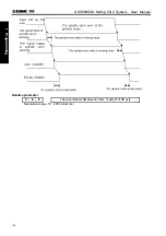
The signal shift relationship of the spindle working
Time sequence figure
Summary of Contents for 980MDc
Page 19: ...GSK980MDc Milling CNC User Manual XVIII ...
Page 20: ...1 I Programming Programming Ⅰ ...
Page 21: ...GSK980MDc Milling CNC System User Manual 2 I Programming ...
Page 139: ...GSK980MDc Milling CNC System User Manual 120 I Programming ...
Page 191: ...GSK980MDc Milling CNC System User Manual 172 I Programming ...
Page 192: ...173 Ⅱ Operation Ⅱ Operation ...
Page 193: ...GSK980MDc Milling CNC System User Manual 174 Ⅱ Operation ...
Page 200: ...Chapter 1 Operation Mode and Display 181 Ⅱ Operation ...
Page 201: ...GSK980MDc Milling CNC System User Manual 182 Ⅱ Operation ...
Page 249: ...GSK980MDc Milling CNC System User Manual 230 Ⅱ Operation ...
Page 253: ...GSK980MDc Milling CNC System User Manual 234 Ⅱ Operation ...
Page 259: ...GSK980MDc Milling CNC System User Manual 240 Ⅱ Operation ...
Page 265: ...GSK980MDc Milling CNC System User Manual 246 Ⅱ Operation ...
Page 293: ...GSK980MDc Milling CNC System User Manual 274 Ⅱ Operation ...
Page 295: ...GSK980MDc Milling CNC System User Manual 276 Ⅱ Operation ...
Page 319: ...GSK980MDc Milling CNC System User Manual 300 Ⅱ Operation ...
Page 320: ...301 Ⅲ Installation Ⅲ Installation ...
Page 321: ...GSK980MDc Milling CNC System User Manual 302 Ⅲ Installation ...
Page 345: ...GSK980MDc Milling CNC System User Manual 326 Ⅲ Installation ...
Page 391: ...GSK980MDc Milling CNC System User Manual 372 Ⅲ Installation ...
Page 392: ...Appendix 373 Appendix Appendix ...
Page 393: ...GSK980MDc Milling CNC System User Manual 374 Appendix ...
Page 394: ...Appendix 375 Appendix Appendix 1 Outline Dimension of GSK980MDc L N ...


