Chapter 3 G Command
83
I Programming
Related explanation:
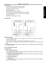
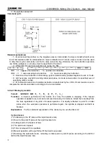
(1) This cycle is used to be bore a hole. The command operation is basically same with G81, only
spindle rotation status is different. After cut feeds to the bottom of a hole, the M05 is executed (spindle
stops), then the point R plane is retracted at the rapid traverse, the M03 is then performed (spindle rotates
positively) regardless of the currently spindle rotation status and the positive or negative rotation are
specified before the canned cycle.
(2) The command Q and P are disabled in this cycle, but its value is reserved as canned cycle modal
value.
3.24.2.10 Back Boring Cycle G87
Command format
G87 X_ Y_ Z_ R_ Q_ P_ F_ L_
X_
Y_
:
hole’s positioning data.
Z
:
hole depth. Incremental specifies distance between point R plane and hole bottom or absolute value
specifies coordinates of hole bottom.
R
:
Incremental specifies distance between point R plane and hole bottom or absolute value specifies
coordinates of point R plane.
Q
:
Offset amount of hole bottom.
P
:
Pause time of hole bottom.
F
:
Cutting feedrate.
L
:
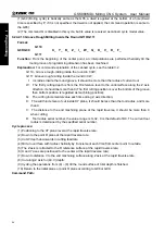
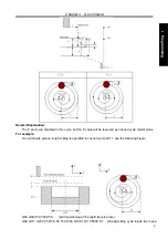
L means quantity of holing from starting point and point set by G87. L means times of currently
circular holing when G87 does not set holing point.
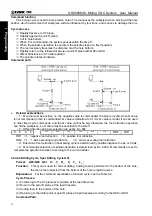
Command function
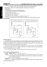
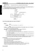
Back boring cycle is used to boring precise hole, and the tool safely retracts to the initial plane after
machining completion.
Cycle process
Rapidly position to XY plane;
⑴
The spindle orientation is done and stops at the fixed position after XY plane positions;
⑵
Traverse Q distance;
⑶
Rapidly traverse to point R;
⑷
Traverse Q distance;
⑸
Spindle rotates CW;
⑹
Execute boring cycle
⑺
to point Z;
When P is commanded, the system pauses at P time;
⑻
⑼
The spindle orientation is executed, it stops at the fixed position;
⑽
Traverse Q distance;
⑾
Return to initial plane;
⑿
Offset Q distance to XY initial position;
Summary of Contents for 980MDc
Page 19: ...GSK980MDc Milling CNC User Manual XVIII ...
Page 20: ...1 I Programming Programming Ⅰ ...
Page 21: ...GSK980MDc Milling CNC System User Manual 2 I Programming ...
Page 139: ...GSK980MDc Milling CNC System User Manual 120 I Programming ...
Page 191: ...GSK980MDc Milling CNC System User Manual 172 I Programming ...
Page 192: ...173 Ⅱ Operation Ⅱ Operation ...
Page 193: ...GSK980MDc Milling CNC System User Manual 174 Ⅱ Operation ...
Page 200: ...Chapter 1 Operation Mode and Display 181 Ⅱ Operation ...
Page 201: ...GSK980MDc Milling CNC System User Manual 182 Ⅱ Operation ...
Page 249: ...GSK980MDc Milling CNC System User Manual 230 Ⅱ Operation ...
Page 253: ...GSK980MDc Milling CNC System User Manual 234 Ⅱ Operation ...
Page 259: ...GSK980MDc Milling CNC System User Manual 240 Ⅱ Operation ...
Page 265: ...GSK980MDc Milling CNC System User Manual 246 Ⅱ Operation ...
Page 293: ...GSK980MDc Milling CNC System User Manual 274 Ⅱ Operation ...
Page 295: ...GSK980MDc Milling CNC System User Manual 276 Ⅱ Operation ...
Page 319: ...GSK980MDc Milling CNC System User Manual 300 Ⅱ Operation ...
Page 320: ...301 Ⅲ Installation Ⅲ Installation ...
Page 321: ...GSK980MDc Milling CNC System User Manual 302 Ⅲ Installation ...
Page 345: ...GSK980MDc Milling CNC System User Manual 326 Ⅲ Installation ...
Page 391: ...GSK980MDc Milling CNC System User Manual 372 Ⅲ Installation ...
Page 392: ...Appendix 373 Appendix Appendix ...
Page 393: ...GSK980MDc Milling CNC System User Manual 374 Appendix ...
Page 394: ...Appendix 375 Appendix Appendix 1 Outline Dimension of GSK980MDc L N ...


