GSK980MDc Milling CNC System User Manual
436
Appendix
11.2.18 Spindle Exact Stop
z
Related signal
z
Function description
The spindle positioning function is realizable in the speed mode of the servo spindle. The spindle
rotary output is cancelled in the spindle exact stop. The spindle exact stop id cancelled in the spindle rotary
output. After the spindle positioning signal STAO is output, the alarm A0.4 (COIN (X5.2) is detected
overtime in spindle positioning) will be issued if the completion signal COIN is not detected at the time set
by DT14.
11.2.19 External MPG Control
z
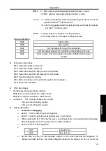
Related signal
z
Function description
The standard ladder diagram supports external MPG of 3-axis (X, Y, Z), PSG-100-05E/L, ZSSY2080
external MPG can be matched. Please refer to the related data for the wiring of the MPG.
11.2.20 Cs Axis Switching
z
Related signals
Signal
type
Symbol Significance Pin-out
No.
PLC
State
CNC
Diagnosis
Exact stop key on the panel
X25.7
Input
signal
COIN
Completion signal of the spindle
positioning
CN15.8
X5.2
STAO Start signal of the spindle positioning CN62.37
Y3.0
Output
signal
Indicator signal of the spindle exact
stop
Y21.3
Input
command
M19
Command of the spindle exact stop
Signal
types
Symbol Significance Pin-out
No.
PLC
State
C NC
Diagnosis
EHDX
External MPG X-axis selection
CN31.5
X6.0
EHDY
External MPG Y-axis selection
CN31.6
X6.1
EHDZ
External MPG Z-axis selection
CN31.8
X6.2
EMP0
External MPG/increment ×1
CN31.9
X6.3
EMP1
External MPG/increment ×10
CN31.22
X6.4
Input
signal
EMP2
External MPG/increment×100
CN31.23
X6.5
Summary of Contents for 980MDc
Page 19: ...GSK980MDc Milling CNC User Manual XVIII ...
Page 20: ...1 I Programming Programming Ⅰ ...
Page 21: ...GSK980MDc Milling CNC System User Manual 2 I Programming ...
Page 139: ...GSK980MDc Milling CNC System User Manual 120 I Programming ...
Page 191: ...GSK980MDc Milling CNC System User Manual 172 I Programming ...
Page 192: ...173 Ⅱ Operation Ⅱ Operation ...
Page 193: ...GSK980MDc Milling CNC System User Manual 174 Ⅱ Operation ...
Page 200: ...Chapter 1 Operation Mode and Display 181 Ⅱ Operation ...
Page 201: ...GSK980MDc Milling CNC System User Manual 182 Ⅱ Operation ...
Page 249: ...GSK980MDc Milling CNC System User Manual 230 Ⅱ Operation ...
Page 253: ...GSK980MDc Milling CNC System User Manual 234 Ⅱ Operation ...
Page 259: ...GSK980MDc Milling CNC System User Manual 240 Ⅱ Operation ...
Page 265: ...GSK980MDc Milling CNC System User Manual 246 Ⅱ Operation ...
Page 293: ...GSK980MDc Milling CNC System User Manual 274 Ⅱ Operation ...
Page 295: ...GSK980MDc Milling CNC System User Manual 276 Ⅱ Operation ...
Page 319: ...GSK980MDc Milling CNC System User Manual 300 Ⅱ Operation ...
Page 320: ...301 Ⅲ Installation Ⅲ Installation ...
Page 321: ...GSK980MDc Milling CNC System User Manual 302 Ⅲ Installation ...
Page 345: ...GSK980MDc Milling CNC System User Manual 326 Ⅲ Installation ...
Page 391: ...GSK980MDc Milling CNC System User Manual 372 Ⅲ Installation ...
Page 392: ...Appendix 373 Appendix Appendix ...
Page 393: ...GSK980MDc Milling CNC System User Manual 374 Appendix ...
Page 394: ...Appendix 375 Appendix Appendix 1 Outline Dimension of GSK980MDc L N ...

