Chapter 3 Parameter
343
Ⅲ
Inst
allation
[Example] When data parameters
№
6044=2000,
№
6045=300,
№
6046=100 are set,
M2000
→
O300
M2001
→
O301
M2002
→
O302
:
M2099
→
O399
Specify the subprogram call of the above listed 100 groups.
Note
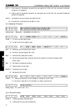
1. If the system satisfies the following conditions, the calls based on this setting are invalid.
The value exceed the data scope is set in parameter
①
Whe
②
n (
№
6045+(
№
6046-1)>9999
2. M execution explanations:
Set called M range
Execution result
M00, M01, M02, M29, M30, M98, M99
The system executes basic M function instead of M calling.
M9000
~
M9999
Call a macro program and the called program number is
the command value of M code.
Other M codes
The system executes M calling subprograms instead of
basic M function.
8
0 1
0
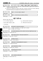
Setting the PLC control axis DI/DO channel 1~4 of each axis
Setting range
:
0
~
4, When set to 0, the channel is invalid
3.2 Parameter Description (by Function Sequence)
3.2.1 Axis Control Logic
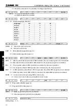
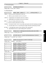
0 0 0 5
PCMD ***
***
ABP5 ABP4 ABPZ ABPY ABPX
ABPn =1
:
Output axis pulse by two right-angle intersection phases(need restart);
=0
:
Output axis pulse by pulse and direction (need restart).
PCMD =1
:
Axial output wave form is pulse;
=0
:
Axial output wave form is square.
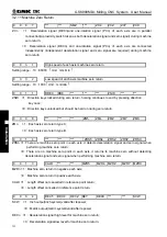
0 0 0 8
***
***
***
DIR5
DIR4 DIRZ
DIRY DIRX
DIRn =1
:
Direction signal (DIR)is high level as each axis moves positively;
=0
:
Direction signal (DIR)is low level as each axis moves negatively.
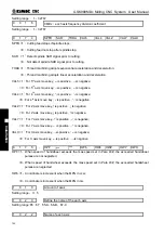
0 0 0 9
***
***
***
ALM5 ALM4 ALMZ ALMY ALMX
ALMn =1
:
each axis low level alarm signal;
=0
:
each axis high level alarm signal.
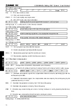
0 0 1 5
CMRx
:
each axis multiplier coefficient
Summary of Contents for 980MDc
Page 19: ...GSK980MDc Milling CNC User Manual XVIII ...
Page 20: ...1 I Programming Programming Ⅰ ...
Page 21: ...GSK980MDc Milling CNC System User Manual 2 I Programming ...
Page 139: ...GSK980MDc Milling CNC System User Manual 120 I Programming ...
Page 191: ...GSK980MDc Milling CNC System User Manual 172 I Programming ...
Page 192: ...173 Ⅱ Operation Ⅱ Operation ...
Page 193: ...GSK980MDc Milling CNC System User Manual 174 Ⅱ Operation ...
Page 200: ...Chapter 1 Operation Mode and Display 181 Ⅱ Operation ...
Page 201: ...GSK980MDc Milling CNC System User Manual 182 Ⅱ Operation ...
Page 249: ...GSK980MDc Milling CNC System User Manual 230 Ⅱ Operation ...
Page 253: ...GSK980MDc Milling CNC System User Manual 234 Ⅱ Operation ...
Page 259: ...GSK980MDc Milling CNC System User Manual 240 Ⅱ Operation ...
Page 265: ...GSK980MDc Milling CNC System User Manual 246 Ⅱ Operation ...
Page 293: ...GSK980MDc Milling CNC System User Manual 274 Ⅱ Operation ...
Page 295: ...GSK980MDc Milling CNC System User Manual 276 Ⅱ Operation ...
Page 319: ...GSK980MDc Milling CNC System User Manual 300 Ⅱ Operation ...
Page 320: ...301 Ⅲ Installation Ⅲ Installation ...
Page 321: ...GSK980MDc Milling CNC System User Manual 302 Ⅲ Installation ...
Page 345: ...GSK980MDc Milling CNC System User Manual 326 Ⅲ Installation ...
Page 391: ...GSK980MDc Milling CNC System User Manual 372 Ⅲ Installation ...
Page 392: ...Appendix 373 Appendix Appendix ...
Page 393: ...GSK980MDc Milling CNC System User Manual 374 Appendix ...
Page 394: ...Appendix 375 Appendix Appendix 1 Outline Dimension of GSK980MDc L N ...


