Chapter 3 G Command
93
I Programming
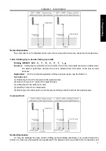
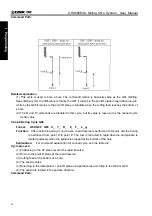
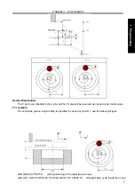
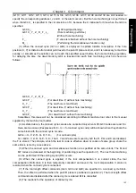
G90 G00 X0 Y0 Z50
;
(
G00 rapidly position
)
G99 G117 X50 Y50 R5 Z-50 I20 J50 W20 Q10 K10 C20 E2 F800 D1
;
(
execute the rough milling
cycle of outer convex plate D1=5
)
G80 X50 Y50 Z50
;
(
cancel fixed cycle, return from point R plane
)
M30
;
3.24.2.17 Rectangular Roughing G132/G133
Command format
:
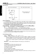
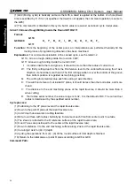
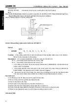
G132
G98/G99 X_ Y_ Z_ R_ I_ J_ A_ B_ W_ Q_ K_ C_ U_ E_ D_ F_
G133
Command function: the tool executes the linear cutting cycle from starting at the specified parameter data
till the programmed rectangular convex plane is machined completed.
Command explanation: related commands are referred to Table 3-2.
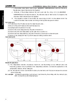
G132
:
outer rectangle roughing CCW
G133
:
outer rectangle roughing CW
XY
:
start-up coordinates in XY plane
I
:
X-axis width of outer rectangle roughing(it is more than 0, and its absolute value is done when it is
negative
)
J
:
Y-axis width of outer rectangle roughing
(
it is more than 0, and its absolute value is done when it is
negative
)
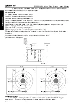
A: X-axis width of blank
(
it is more than 0, and its absolute value is done when it is negative
)
B
:
Y-axis width of blank
(
it is more than 0, and its absolute value is done when it is negative
)
E
:
Allowance in XY plane of outer rectangle roughing
(
it is more than 0, and its absolute value is done
when it is negative. The value set by No.5124 is defaulted when it is not specified
)
W
:
Z-axis depth of first cutting is the distance downward from R reference plane, and should be more
than 0, its absolute value is done when it is negative (when the first cutting depth exceeds groove bottom
position, directly machining the groove position is done
)
Q
:
Z-axis cutting depth increment every time. its absolute value is done when it is negative
K
:
Cutting width increment in XY plane
(
it should be less than tool diameter, its absolute value is done
when it is negative; when K is not specified, K is defaulted to tool radius D
)
Summary of Contents for 980MDc
Page 19: ...GSK980MDc Milling CNC User Manual XVIII ...
Page 20: ...1 I Programming Programming Ⅰ ...
Page 21: ...GSK980MDc Milling CNC System User Manual 2 I Programming ...
Page 139: ...GSK980MDc Milling CNC System User Manual 120 I Programming ...
Page 191: ...GSK980MDc Milling CNC System User Manual 172 I Programming ...
Page 192: ...173 Ⅱ Operation Ⅱ Operation ...
Page 193: ...GSK980MDc Milling CNC System User Manual 174 Ⅱ Operation ...
Page 200: ...Chapter 1 Operation Mode and Display 181 Ⅱ Operation ...
Page 201: ...GSK980MDc Milling CNC System User Manual 182 Ⅱ Operation ...
Page 249: ...GSK980MDc Milling CNC System User Manual 230 Ⅱ Operation ...
Page 253: ...GSK980MDc Milling CNC System User Manual 234 Ⅱ Operation ...
Page 259: ...GSK980MDc Milling CNC System User Manual 240 Ⅱ Operation ...
Page 265: ...GSK980MDc Milling CNC System User Manual 246 Ⅱ Operation ...
Page 293: ...GSK980MDc Milling CNC System User Manual 274 Ⅱ Operation ...
Page 295: ...GSK980MDc Milling CNC System User Manual 276 Ⅱ Operation ...
Page 319: ...GSK980MDc Milling CNC System User Manual 300 Ⅱ Operation ...
Page 320: ...301 Ⅲ Installation Ⅲ Installation ...
Page 321: ...GSK980MDc Milling CNC System User Manual 302 Ⅲ Installation ...
Page 345: ...GSK980MDc Milling CNC System User Manual 326 Ⅲ Installation ...
Page 391: ...GSK980MDc Milling CNC System User Manual 372 Ⅲ Installation ...
Page 392: ...Appendix 373 Appendix Appendix ...
Page 393: ...GSK980MDc Milling CNC System User Manual 374 Appendix ...
Page 394: ...Appendix 375 Appendix Appendix 1 Outline Dimension of GSK980MDc L N ...

