Chapter 8 Machine Zero Return Operation
275
Ⅱ
Operation
CHAPTER 8 MACHINE ZERO RETURN OPERATION
8.1 Machine Zero
The machine coordinate system
is a basic coordinate system for CNC coordinate calculation. It is
an inherent coordinate system of the machine. The origin of the machine coordinate system
is called
machine zero
(or machine reference point). It is defined by the zero return switches fixed
on the machine. Usually the switch is fixed on the positive max. Strokes of X, Y, Z axes.
Note: the mechanical zero is called “machine zero”.
8.2 Machine Zero Return Steps
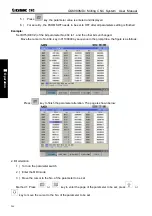
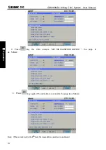
1. Press
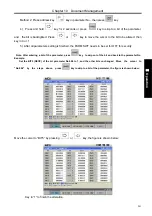
key, it enters the Machine zero mode, the bottom line of the screen page shows
“REF”, the figure is shown below:
2. Press
or
or
key to select the machine zero of X, Y or Z axis
3. The machine moves along the machine zero direction, and returns to the machine zero via the
deceleration signal, zero signal detection. And the axis stops with the machine zero finish indicator
lighting up.
Machine zero finish indicators
Note 1
:
If the machine zero is not fixed on the machine, machine zero operation B/C/D is unallowed.
Note 2
:
While the coordinate is moved out from the machine zero, the machine zero finish indicators go out.
Note 3
:
After the machine zero operation, the cancellation of the tool length offset for the
CNC is set by the BIT7 of the bit parameter No.13
Note 4
:
See details in the 3rd part INSTALLATION AND CONNECTION for the parameters concerning with
the machine zero.
Note 5: When machine zero return, bit parameter
№
011 ZNIK determines whether axis movement is locked
automatically.
Summary of Contents for 980MDc
Page 19: ...GSK980MDc Milling CNC User Manual XVIII ...
Page 20: ...1 I Programming Programming Ⅰ ...
Page 21: ...GSK980MDc Milling CNC System User Manual 2 I Programming ...
Page 139: ...GSK980MDc Milling CNC System User Manual 120 I Programming ...
Page 191: ...GSK980MDc Milling CNC System User Manual 172 I Programming ...
Page 192: ...173 Ⅱ Operation Ⅱ Operation ...
Page 193: ...GSK980MDc Milling CNC System User Manual 174 Ⅱ Operation ...
Page 200: ...Chapter 1 Operation Mode and Display 181 Ⅱ Operation ...
Page 201: ...GSK980MDc Milling CNC System User Manual 182 Ⅱ Operation ...
Page 249: ...GSK980MDc Milling CNC System User Manual 230 Ⅱ Operation ...
Page 253: ...GSK980MDc Milling CNC System User Manual 234 Ⅱ Operation ...
Page 259: ...GSK980MDc Milling CNC System User Manual 240 Ⅱ Operation ...
Page 265: ...GSK980MDc Milling CNC System User Manual 246 Ⅱ Operation ...
Page 293: ...GSK980MDc Milling CNC System User Manual 274 Ⅱ Operation ...
Page 295: ...GSK980MDc Milling CNC System User Manual 276 Ⅱ Operation ...
Page 319: ...GSK980MDc Milling CNC System User Manual 300 Ⅱ Operation ...
Page 320: ...301 Ⅲ Installation Ⅲ Installation ...
Page 321: ...GSK980MDc Milling CNC System User Manual 302 Ⅲ Installation ...
Page 345: ...GSK980MDc Milling CNC System User Manual 326 Ⅲ Installation ...
Page 391: ...GSK980MDc Milling CNC System User Manual 372 Ⅲ Installation ...
Page 392: ...Appendix 373 Appendix Appendix ...
Page 393: ...GSK980MDc Milling CNC System User Manual 374 Appendix ...
Page 394: ...Appendix 375 Appendix Appendix 1 Outline Dimension of GSK980MDc L N ...


