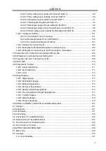
CONTENTS
IX
3.24.2.14 Fine-milling Cycle Inside Full Circle G112/G113................................................88
3.24.2.15 Fine-milling Cycle Outside Circle G114/G115....................................................89
3.24.2.16 Roughing Cycle Outside Circle G116/G117.......................................................91
3.24.2.17 Rectangular Roughing G132/G133 ...................................................................93
3.24.2.18 Rectangle Groove Rough-milling G134/G135 ...................................................95
3.24.2.19 Rectangle Groove Inner Fine-milling Cycle G136/G137....................................98
3.24.2.20 Finish-milling Cycle Outside the Rectangle G138/G139....................................99
3.24.3 Continuous Drilling ...................................................................................................... 101
3.24.3.1 Line Series Punch (L function) .......................................................................... 101
3.24.3.2 Rectangle Series Punch (G140/G141) .............................................................. 102
3.24.3.3 Arc Serial Punching (G142/G143) ..................................................................... 103
3.24.4 Cautions for Canned Cycle.......................................................................................... 104
3.24.5 Examples for Modal Data Specified in Canned Cycle.................................................. 106
3.24.6 Examples for Canned Cycle and Tool Length Compensation...................................... 107
3.25 Absolute and Incremental Commands G90 and G91............................................................. 108
3.26 Workpiece Coordinate System Setting G92 .......................................................................... 109
3.27 Feed per min. G94, Feed per rev. G95 .................................................................................. 109
3.28 G98, G99 ............................................................................................................................... 110
3.29 Chamfering Function ............................................................................................................. 110
3.29.1 Linear Chamfering ....................................................................................................... 111
3.29.2 Arc Chamfering............................................................................................................ 111
3.29.3 Limit............................................................................................................................. 112
3.30 Rigid Tapping ......................................................................................................................... 112
3.30.1 Rigid Tapping............................................................................................................... 113
3.30.2 Peck Rigid Tapping...................................................................................................... 113
3.30.3 Address Explanation.................................................................................................... 115
3.30.4 Technical Specification ................................................................................................ 115
3.30.5 Specify a Rigid Tapping Mode ..................................................................................... 116
3.30.6 The Cancellation of Rigid Tapping Mode ..................................................................... 117
3.30.7 F and G Signals........................................................................................................... 118
3.30.8 Alarm Message............................................................................................................ 118
3.30.9 Program Example........................................................................................................ 119
CHAPTER 4 CONTROL FUNCTION of ADDITIONAL AXIS.......................................................... 121
4.1 General.................................................................................................................................... 121
4.2 Axis Name ............................................................................................................................... 121
4.3 Axis Display ............................................................................................................................. 121
4.4 Axis Startup.............................................................................................................................. 122
4.5 Linear Axis of The Additional Axis ............................................................................................ 122
4.6 Rotation Axis of The Additional Axis......................................................................................... 123
4.7 The Zero Return D of Rotation Axis .........................................................................................124
4.8 The Function of Cs Axis........................................................................................................... 125
CHAPTER 5 MACRO PROGRAM................................................................................................. 129
5.1 Macro Call ............................................................................................................................... 129
5.2 Variables.................................................................................................................................. 133
5.2.1 Null Variables................................................................................................................. 137
Summary of Contents for 980MDc
Page 19: ...GSK980MDc Milling CNC User Manual XVIII ...
Page 20: ...1 I Programming Programming Ⅰ ...
Page 21: ...GSK980MDc Milling CNC System User Manual 2 I Programming ...
Page 139: ...GSK980MDc Milling CNC System User Manual 120 I Programming ...
Page 191: ...GSK980MDc Milling CNC System User Manual 172 I Programming ...
Page 192: ...173 Ⅱ Operation Ⅱ Operation ...
Page 193: ...GSK980MDc Milling CNC System User Manual 174 Ⅱ Operation ...
Page 200: ...Chapter 1 Operation Mode and Display 181 Ⅱ Operation ...
Page 201: ...GSK980MDc Milling CNC System User Manual 182 Ⅱ Operation ...
Page 249: ...GSK980MDc Milling CNC System User Manual 230 Ⅱ Operation ...
Page 253: ...GSK980MDc Milling CNC System User Manual 234 Ⅱ Operation ...
Page 259: ...GSK980MDc Milling CNC System User Manual 240 Ⅱ Operation ...
Page 265: ...GSK980MDc Milling CNC System User Manual 246 Ⅱ Operation ...
Page 293: ...GSK980MDc Milling CNC System User Manual 274 Ⅱ Operation ...
Page 295: ...GSK980MDc Milling CNC System User Manual 276 Ⅱ Operation ...
Page 319: ...GSK980MDc Milling CNC System User Manual 300 Ⅱ Operation ...
Page 320: ...301 Ⅲ Installation Ⅲ Installation ...
Page 321: ...GSK980MDc Milling CNC System User Manual 302 Ⅲ Installation ...
Page 345: ...GSK980MDc Milling CNC System User Manual 326 Ⅲ Installation ...
Page 391: ...GSK980MDc Milling CNC System User Manual 372 Ⅲ Installation ...
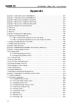
Page 392: ...Appendix 373 Appendix Appendix ...
Page 393: ...GSK980MDc Milling CNC System User Manual 374 Appendix ...
Page 394: ...Appendix 375 Appendix Appendix 1 Outline Dimension of GSK980MDc L N ...


