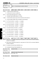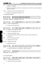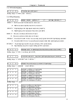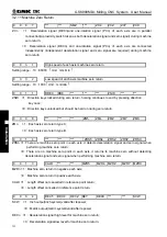
Chapter 4 Machine Debugging
355
Ⅲ
Inst
allation
CHAPTER 4 MACHINE DEBUGGING
The trial run methods and steps at initial power on for this GSK980MDc are described in this chapter.
The corresponding operation can be performed after the debugging by the following steps.
4.1 Emergency Stop and Stroke Limit
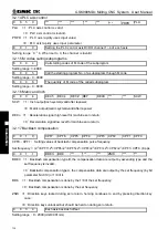
This GSK980MDc system has software limit function, it is suggested that the stroke limit switches are
fixed in the positive or negative axes for hardware limit. The connection is shown in follows:
(
The chart is
designed for X, Y, Z axes
)
Fig. 4-1
So the MESP of bit parameter No.172 should be set to 0.
And the CNC diagnostic message ESP can monitor the state of emergency stop input signal.
In Manual or MPG mode, slowly move the axes to test the validity of stroke limit
switch, correctness of alarm display, validity of overtravel release button. When the overtravel
occurs or Emergency Stop button is pressed, “emergency stop” alarm will be issued by CNC system.
The alarm can be cancelled by pressing down the Overtravel button and moving reversely.
4.2 Drive Unit Setting
Set BIT4
~
BIT0 of bit parameter No.009 according to alarm logic level of drive unit. The BIT4
~
BIT0 of bit parameter No.009 for our drive unit are all set for 1 .
If the machine moving direction is not consistent with the moving command, modify the BIT4
~
BIT0
of bit parameter No.008
,
BIT4
~
BIT0 of bit parameter No.175, BIT4
~
BIT0 of bit parameter No.174.
4.3 Gear Ratio Adjustment
4.3.1 Servo Feed Axis
The data parameter
№
015
~
№
016 can be modified for electronic gear ratio adjustment to meet the
different mechanical transmission ratio if the machine travel distance is not consistent with the displacement
distance displayed by CNC coordinate.
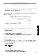
Calculation formula of CNC:
D
M
Z
Z
L
CMD
CMR
×
×
=
360
α
δ
CMR
CMD
Z
Z
L
D
M
×
×
×
=
360
δ
α
CMR: command multiplier coefficient (data parameter
№
15)
CMD: command frequency division coefficient (data parameter
№
16)
Summary of Contents for 980MDc
Page 19: ...GSK980MDc Milling CNC User Manual XVIII ...
Page 20: ...1 I Programming Programming Ⅰ ...
Page 21: ...GSK980MDc Milling CNC System User Manual 2 I Programming ...
Page 139: ...GSK980MDc Milling CNC System User Manual 120 I Programming ...
Page 191: ...GSK980MDc Milling CNC System User Manual 172 I Programming ...
Page 192: ...173 Ⅱ Operation Ⅱ Operation ...
Page 193: ...GSK980MDc Milling CNC System User Manual 174 Ⅱ Operation ...
Page 200: ...Chapter 1 Operation Mode and Display 181 Ⅱ Operation ...
Page 201: ...GSK980MDc Milling CNC System User Manual 182 Ⅱ Operation ...
Page 249: ...GSK980MDc Milling CNC System User Manual 230 Ⅱ Operation ...
Page 253: ...GSK980MDc Milling CNC System User Manual 234 Ⅱ Operation ...
Page 259: ...GSK980MDc Milling CNC System User Manual 240 Ⅱ Operation ...
Page 265: ...GSK980MDc Milling CNC System User Manual 246 Ⅱ Operation ...
Page 293: ...GSK980MDc Milling CNC System User Manual 274 Ⅱ Operation ...
Page 295: ...GSK980MDc Milling CNC System User Manual 276 Ⅱ Operation ...
Page 319: ...GSK980MDc Milling CNC System User Manual 300 Ⅱ Operation ...
Page 320: ...301 Ⅲ Installation Ⅲ Installation ...
Page 321: ...GSK980MDc Milling CNC System User Manual 302 Ⅲ Installation ...
Page 345: ...GSK980MDc Milling CNC System User Manual 326 Ⅲ Installation ...
Page 391: ...GSK980MDc Milling CNC System User Manual 372 Ⅲ Installation ...
Page 392: ...Appendix 373 Appendix Appendix ...
Page 393: ...GSK980MDc Milling CNC System User Manual 374 Appendix ...
Page 394: ...Appendix 375 Appendix Appendix 1 Outline Dimension of GSK980MDc L N ...


