Chapter 3 G Command
41
I Programming
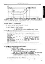
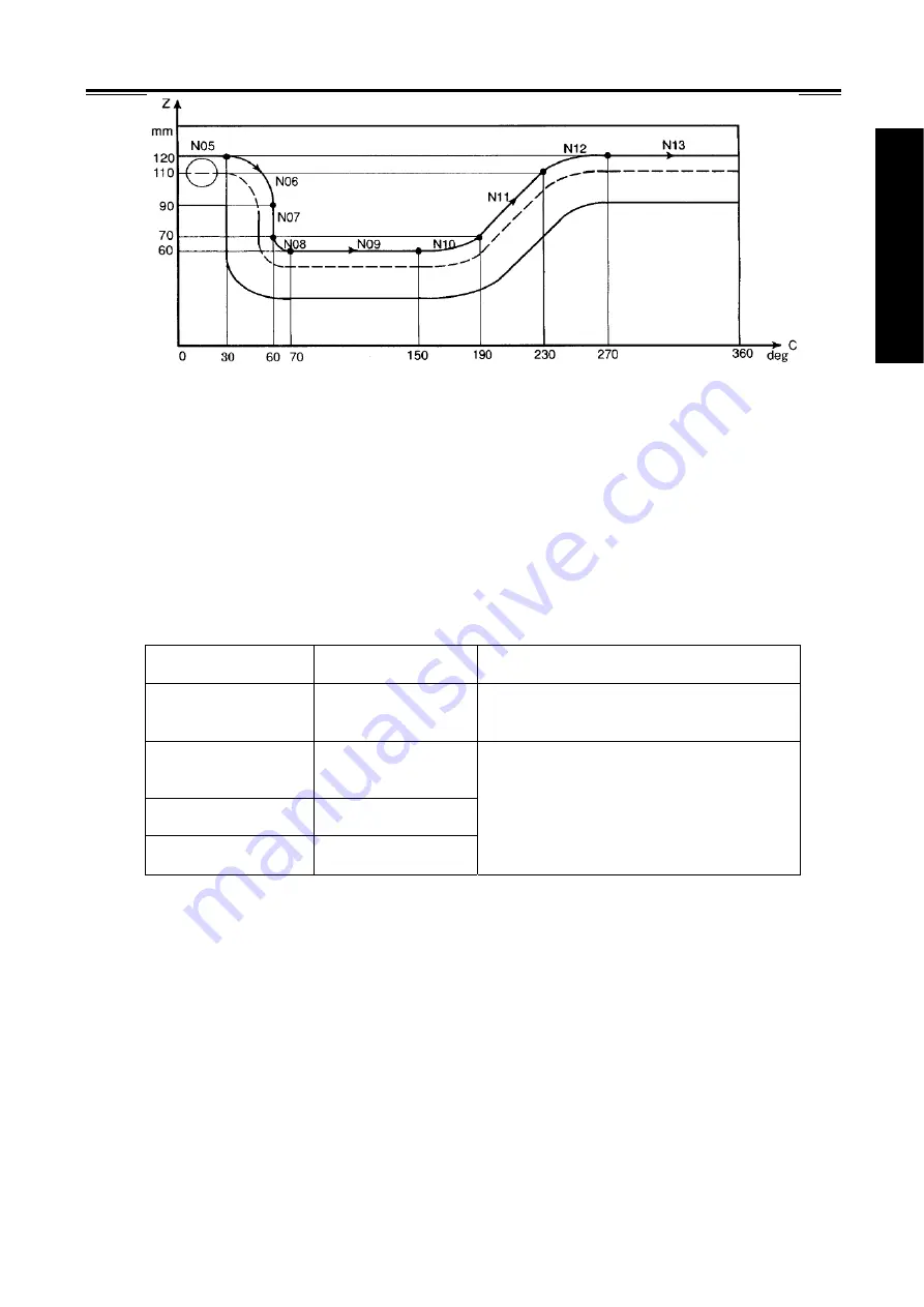
The above figure is side stretched-out drawing of the cylinder in the above example. It can be seen
from the figure that: when travel amount of rotary axis (C axis) specified by angle is converted to a distance
of a linear axis on the outer surface, the interpolation formed by it and another linear axis (Z axis) can be
seen as an interpolation in the plane coordinate system Z-X on plane G18.
3.7 Programmable Data Input G10
G10 can modify some data value when a program is executed.
Command
format
:
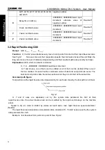
G10 Lm Pn Rx;
Command
explanation
:
m
:
modified data type
;
n
:
data serial number
x
:
input value is determined to absolute or increment by G90/G91.
3.7.1 Modifying Tool Compensation Data
Tool compensation
type
Command format
Explanation
Geometry
compensation value
of H command
G10 L10 P_
R_
P
:
tool compensation number
Geometry
compensation value
of D command
G10 L12 P_
R_
Wear compensation
value of H command
G10 L11 P_ R_
Wear compensation
value of D command
G10 L13 P_
R_
R
:
Tool compensation value is sum of it
adding the value of specified tool
compensation number in absolute value
command
(
G90
)
or incremental value
command
(
G91
)
.
Note: Geometry compensation value of tool radius compensation D cannot be negative, otherwise, an
alarm occurs.
3.7.2 Modifying a Workingpiece Coordinate System
Command format
:
G10 L2 P n IP_;
n=0: modify workpiece zero float
;
n=1~6: modify workpiece zero floats of workpiece coordinate system 1~6.
IP
:
coordinate setting value
,
IP value is a setting value of corresponding coordinate system;
When G91 is executed, the specified value of setting value +IP of current
coordinate system is a setting value of a new coordinate system.
Corresponding coordinate system’s value of default axis does not change.
When P is defaulted, a coordinate system is not set, which is taken an alarm.
An alarm occurs when the specified P is beyond 0~6;
An alarm occurs when the specified coordinate data is beyond the above range;
When a program is executed and value of current coordinate system is changed, and the absolute
Summary of Contents for 980MDc
Page 19: ...GSK980MDc Milling CNC User Manual XVIII ...
Page 20: ...1 I Programming Programming Ⅰ ...
Page 21: ...GSK980MDc Milling CNC System User Manual 2 I Programming ...
Page 139: ...GSK980MDc Milling CNC System User Manual 120 I Programming ...
Page 191: ...GSK980MDc Milling CNC System User Manual 172 I Programming ...
Page 192: ...173 Ⅱ Operation Ⅱ Operation ...
Page 193: ...GSK980MDc Milling CNC System User Manual 174 Ⅱ Operation ...
Page 200: ...Chapter 1 Operation Mode and Display 181 Ⅱ Operation ...
Page 201: ...GSK980MDc Milling CNC System User Manual 182 Ⅱ Operation ...
Page 249: ...GSK980MDc Milling CNC System User Manual 230 Ⅱ Operation ...
Page 253: ...GSK980MDc Milling CNC System User Manual 234 Ⅱ Operation ...
Page 259: ...GSK980MDc Milling CNC System User Manual 240 Ⅱ Operation ...
Page 265: ...GSK980MDc Milling CNC System User Manual 246 Ⅱ Operation ...
Page 293: ...GSK980MDc Milling CNC System User Manual 274 Ⅱ Operation ...
Page 295: ...GSK980MDc Milling CNC System User Manual 276 Ⅱ Operation ...
Page 319: ...GSK980MDc Milling CNC System User Manual 300 Ⅱ Operation ...
Page 320: ...301 Ⅲ Installation Ⅲ Installation ...
Page 321: ...GSK980MDc Milling CNC System User Manual 302 Ⅲ Installation ...
Page 345: ...GSK980MDc Milling CNC System User Manual 326 Ⅲ Installation ...
Page 391: ...GSK980MDc Milling CNC System User Manual 372 Ⅲ Installation ...
Page 392: ...Appendix 373 Appendix Appendix ...
Page 393: ...GSK980MDc Milling CNC System User Manual 374 Appendix ...
Page 394: ...Appendix 375 Appendix Appendix 1 Outline Dimension of GSK980MDc L N ...


