background image

INSTRUCTION MANUAL

EZA2500FC

TDK-Lambda

<Page>

BEFORE USING THE POWER SUPPLY UNIT (Common)

Be sure to read this instruction manual thoroughly before using this product. Pay attention to all cautions and warnings before 
using this product. Incorrect usage could lead to an electrical shock, damage to the unit or a fire hazard.

DANGER

 Never use this product in locations where flammable gas or ignitable substances are present.

INSTALLATION WARNING

• When installing, ensure that work is done in accordance with the instruction manual. When installation is improper, there is 

risk of electric shock and fire.

• Installation shall be done by Service personnel with necessary and appropriate technical training and experience. There is a 

risk of electric shock and fire.

• Do  not  cove r   the  product  with  cloth  or  paper  etc.  Do  not  place  anything  flammable  around.  This  might  cause  damage, 

electric shock or fire.

WARNING on USE

• Do not touch this product or its internal components while circuit in operation, or shortly after shutdown. You may receive 

a burn.

• While this product is operating, keep your hands and face away from it as you may be injured by an unexpected situation.
• There  are  cases  where  high  voltage  charge  remains  inside  the  product.  Therefore,  do  not  touch  even  if  they  are  not  in 

operation as you might get injured due to high voltage and high temperature. 
You might also get electric shock or burn.

• Do  not  make  unauthorized  changes  to  this  product  nor  remove  the  cover  as  you  might  get  an  electric  shock  or  might 

damage the product. We will not be held responsible after the product has been modified, changed or dis-assembled.

• Do not use this product under unusual condition such as emission of smoke or abnormal smell and sound etc. Please stop 

using it immediately and shut off the product.
It  might  lead  to  fire  and  electric  shock.  In  such  cases,  please  contact  us.  Do  not  attempt  repair  by  yourself,  as  it  is 
dangerous for the user.

• Do not operate and store these products in environments where condensation occurs due to moisture and humidity. It might 

lead fire and electric shock.

• Do  not  drop  or  apply  shock  to  this  product.  It  might  cause    failure.  Do  not  operate  these  products  mechanical  stress  is 

applied.

CAUTION on MOUNTING

• Confirm connections to input/output terminals are correct as indicated in the instruction manual before switching on.
• Input  voltage,  Output  current,  Output  power,  ambient  temperature  and  ambient  humidity  should  be  kept  within 

specifications, otherwise the product will be damaged, or cause electric shock or fire.


• Do not use this product in special environment with strong electromagnetic field, corrosive gas or conductive substances 

and direct sunlight, or places where product is exposed to water or rain.

• Mount  this  product  properly  in  accordance  with  the  instruction  manual,  mounting  direction  and  shall  be  properly  be 

ventilated.

• Please shut down the input when connecting input and output of the product.
•   The power supply may cause damage when it intake conductive material, dust and liquid. When use this product, please be 

careful to prevent entry of those materials to inside the product by using filter etc.


 Do not use this product in environments where causes the salt damage.

CAUTION on USE

•   Product individual notes are shown in the instruction manual. If there is any difference with common notes  individual notes 

shall have priority.


Before using this product, be sure to  read the catalog and instruction manual. There is risk of electric shock or damage to 

the product or fire due to improper use.


Input  voltage,  Output  current,  Output  power,  ambient  temperature  and  ambient  humidity  should  be  kept  within 

specifications, otherwise the product will be damaged, or cause electric shock or fire.  


If the built-in fuse is blown, do not use the product even after replacing the fuse as there is risk of abnormality inside. Be 

sure to request repair to our company.

1/23

EZA2500FC

INSTRUCTION MANUAL

V008-04-11/FC

Summary of Contents for EZA2500FC

Page 1: ...ot attempt repair by yourself as it is dangerous for the user Do not operate and store these products in environments where condensation occurs due to moisture and humidity It might lead fire and elec...

Page 2: ...t be overhauled Take care not to apply external abnormal voltage to the output Especially applying reverse voltage or overvoltage more than the rated voltage to the output might cause failure electric...

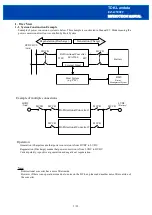
Page 3: ...hat power conversion is from LVDC to HVDC Current polarity is positive at generation and negative at regeneration Note Bi directional converter has a noise filter inside However if there is an operati...

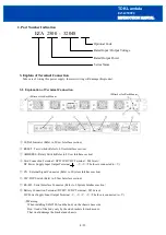
Page 4: ...erminal V V The fuse is connected to V CN External Signal Connector Refer to 9 System Interface section SW DIP Switch Refer to 8 User Interface section RS 485 Serial Interface Connector Refer to 9 Sys...

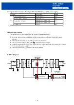
Page 5: ...ng to the terminal of this power supply Use the recommended connectors described in section 3 2 Appropriate Connectors Housing and Terminal Pins for use in this power supply Connector accessories are...

Page 6: ...ormality for some reason the LED will remain lit up After the initialize process the converter will be in waiting mode Power conversion operation will start when the operation command is sent The inte...

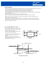
Page 7: ...charging process when battery voltage level reaches the target voltage level Refer to 7 Battery Protection For the Output Side Grid Port 300V or more pre charge is required When external voltage is no...

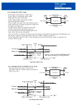
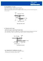
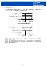
Page 8: ...ge or constant current Also it is possible to set battery over charge and over discharge protection that stops charging and discharging process when battery voltage level reaches the target voltage le...

Page 9: ...current Please set the over voltage protection and under voltage protection to the appropriate values Also please use the protective function of battery together 9 23 Generation Charge Regeneration Di...

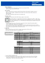
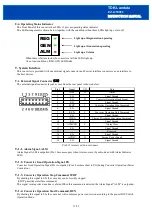
Page 10: ...m state 8 2 Rotary SW The rotary switch functions as the RS 485 address setting for this converter The interface address is composed of 7 bits and can be set within the range 0x00 0x7E range Rotary sw...

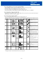
Page 11: ...tion Signal PG is outputted Pin 3 becomes short to SG during Converter Operation Power Conversion 9 1 3 Converter Operation Stop Command STOP By shorting this signal to SG the converter can be forcibl...

Page 12: ...gnal and is hold if input signal released 7 I RUN Conversion is Started at Falling Edge Input Conversion is Stopped at Rising Edge Input 10ms typ 30ms max Chattering removal time 60ms No Voltage Conta...

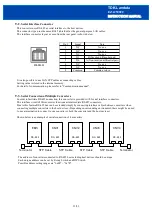
Page 13: ...mediate RS 485 connectors Due to this feature RS 485 bus can be extended simply by connecting interface cables between converters when connecting multiple converters to the host devices Depending on s...

Page 14: ...signal connector ALM signal is triggered open When this happens during power conversion process power conversion stops and the external signal connector PG becomes open Heavy Alarm System Alert cannot...

Page 15: ...shold level is fixed 10 2 8 Converter Stop Command External Signal When Converter Stop Command of the External Signal Connector is detected the Converter Stop Alarm is triggered 10 2 9 Fan Lock If int...

Page 16: ...tem Alert is not covered by Alarm Recovery procedures 11 Explanation of Functions and Precautions 11 1 Input Voltage Range Input voltage range is 36 60VDC for LVDC and 300 380VDC for HVDC Input voltag...

Page 17: ...Please use same size and same length of output wires 3 Please use same size and same length of input wire for each separate converter 11 7 Dynamic Loads At full load or no load conditions and during...

Page 18: ...then gradually decreased to zero When timer is used the unit may be damaged by high rate of change of voltage at turn on off Ramp the voltage even if using a timer Connect V and V as follows primary...

Page 19: ...onverter Bottom View 19 23 Warning When installing EZA2500 load the body on the chassis base side Don t load of the body only by the side brackets for rack mount That would damage the bracket and chas...

Page 20: ...type converter This converter has ventilating holes on the front and rear side panel Keep these two areas freely as much as possible 2 The maximum allowable penetration of mounting screws is 6mm Inco...

Page 21: ...ing 13 1 LVDC Voltage vs LVDC Current Derating 13 2 HVDC Voltage vs HVDC Current Derating 13 3 HVDC Voltage vs LVDC Voltage Derating 13 4 Ambient Temperature vs Output Derating 21 23 0 20 40 60 80 100...

Page 22: ...urthest extent 3 Check secure locking on each insertion by pulling wire softly in order to check that contact does not come off housing Besides check whether there is the backlash in the direction of...

Page 23: ...sis of converter abnormally hot The output might shut down by OTP operation Please re start after allowing time for the unit to cool down sufficiently 7 Check if the output current and output wattage...

Reviews: