32
Description of transmitter - Telemetry data display
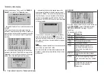
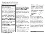
Rev-count sensor
rpm
0
0
0
This display visualises the rotational speed measured by
a rev-count sensor, Order No.
33615
or
33616
, con-
nected to the General Engine module (Order No.
33610
)
or the General Air module (Order No.
33611
).
Note:
For correct display of rotational speed you must first
set the appropriate number of blades by accessing the
Telemetry menu for the sensor.
Vario
0.0
0
m
m
s
This display visualises the data for altitude in m relative
to the location or launch point, and the actual climb /
sink rate in m/s, generated by the integral vario in the
General Engine module (Order No.
33610
) or the Gen-
eral Air module (Order No.
33611
).
ELECTRIC AIR MODUL
RECEIVER
GENERAL
ELECT. AIR
VARIO
GPS
0.0V 0m/3s
BAT1 0m/1s
BAT2
0.0V T2 0°C
T1 0°C
0
1L0.00
2L0.00
3L0.00
4L0.00
5L0.00
6L0.00
ALT 0m
7L0.00
0.0V 0A
0.0V 0m/3s
BAT1 0m/1s
BAT2
0.0V T2 0°C
T1 0°C
0
1H0.00
2H0.00
3H0.00
4H0.00
5H0.00
6H0.00
ALT 0m
7H0.00
0.0V 0A
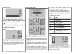
This display visualises the data from an Electric-Air
module, Order No.
33620
, connected to the receiver.
For more information on this module please see the
Appendix, or refer to the product on the Internet at www.
graupner.de.
Depending on the sensors connected to the modules,
the following data may be generated constantly on the
screen:
The actual voltage of up to two batteries (BAT1 and
BAT2); the measurement results from up to two temper-
ature sensors (T1 and T2); the current altitude relative
to the pilot’s location, the model’s climb / descent rate in
m/1 s and m/3 s, and - in the centre of the screen - the
actual current drawn from a power source.
At the right-hand margin you will see an alternating
display of the actual cell voltages of the battery packs
(up to seven cells) connected to balancer sockets 1 (L)
or 2 (H).
The meanings are as follows:
Value
Value
V
Actual voltage
A
Actual current
BAT1 / BAT2
Battery 1 / Battery 2
ALT
Current altitude
m/1s
m/1 sec climb / descent
m/3s
m/3 sec climb / descent
T1 / T2
Temperature at sensor 1 / 2
L / H
Cell voltage of cell 1 … max. 14
L = balancer socket 1
H = balancer socket 2
BAT 1
0.0V
0.0A
0mAh
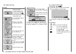
This display visualises the actual voltage, the actual
current drain and the consumed capacity of any battery
connected to the “Battery 1” socket of the Electric Air
module (Order No.
33620
).
Summary of Contents for mx-12 Hott
Page 1: ...Programming Manual 33116 mx 16 HoTT 3 en mx 16...
Page 35: ...35 For your notes...
Page 49: ...49 For your notes...
Page 55: ...55 For your notes...
Page 59: ...59 For your notes...
Page 63: ...63 For your notes...
Page 69: ...69 For your notes...
Page 91: ...91 For your notes...
Page 101: ...101 For your notes...
Page 123: ...123 For your notes...
Page 181: ...181 For your notes...
Page 193: ...193 For your notes...


