171
Programming example - fixed-wing model
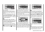
I5
I6
I7
+
trv
I8
free
free
+100% +100%
+100%
+100% +100%
+100% +100%
+100%
free
3
In the third column you can adjust servo travel to suit the
speed controller you are using; alternatively you could
use the “Servo travel” column in the
…
“Servo settings”
menu
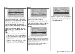
S4
S5
S6
rev cent
+
trav
0%
0%
0%
100% 100%
100% 100%
100% 100%
0%
0%
100% 100%
100% 100%
S7
S8
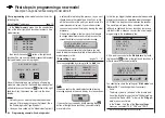
The last stage is to check the settings, so move from
the basic display to “
Servo display
” by simultaneously
touching the
buttons of the left-hand touch-key: in
the switch’s “OFF” position, the control channel you have
selected - in our example this is channel “8” - should be
at -100%, and at the “full-throttle” setting at +100%.
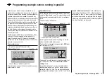
Example 3
Using one of the three-position switches SW 4/5 or
6/7
This variant implements a three-stage solution for
switching an electric motor on and off, and also results
in an “abrupt “ motor start-up … unless the speed con-
troller you are using features what is known as a “soft
start” function.
At the receiving end you need a suitable speed controller.
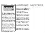
Example 2
Using a two-position switch, SW 2, 3 or 8
This variant implements a pure ON / OFF function, and
results in the motor starting “abruptly” … unless the
speed controller you are using features what is known
as a “soft start” function.
At the receiving end you need either a simple electronic
switch or - if you want a smoother motor start - a suit-
able speed controller.
The settings for this arrangement are entered in the …
“Transmitter control settings”
menu
First check which receiver socket (5 or higher) is avail-
able for connection to your speed controller. If you have
assigned two aileron servos in the “
Base settings
”
menu, and if you have not connected any other auxiliary
function, then this would be channel 6; if your model
features two aileron servos and two flap servos, then
channel 8 would be available for connecting the speed
controller; the latter option is the one we wish to use in
this example.
First set the selected switch to the “OFF” position, then
use the arrow buttons
of the left or right-hand
touch-key to select the desired line in the menu. Touch
the central
SET
button of the right-hand touch-key to
activate “Switch / transmitter control assignment”, then
move the selected switch from the “OFF” position to
the “ON” position. The highlighted field now shows the
switch number together with a symbol which indicates
the direction of switching:
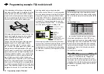
First check which receiver socket (5 or higher) is avail-
able to connect your speed controller. If you have as-
signed two aileron servos in the “
Base settings
” menu,
and if you have not connected any other auxiliary func-
tion, then this would be channel 6; if your model features
two aileron servos and two flap servos, then channel 8
would be available for connecting the speed controller;
the latter option is the one we will use in this example.
Move to the …
“Transmitter control settings”
menu
… and use the arrow buttons
of the left or right-
hand touch-key to select the desired line. Briefly press
the central
SET
button of the right-hand touch-key to
activate “Switch / transmitter control assignment”. Move
the selected three-position switch; the highlighted field
now shows the number of this transmitter control, for
example “Transmitter control 9”.
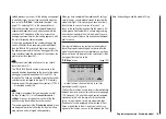
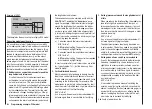
I5
I6
I7
+
trv
I8 ctrl 9
free
free
+100% +100%
+100%
+100% +100%
+100% +100%
+100%
free
In the third column you can adjust servo travel to suit the
speed controller you are using; alternatively you could
use the “Servo travel” column in the
…
Summary of Contents for mx-12 Hott
Page 1: ...Programming Manual 33116 mx 16 HoTT 3 en mx 16...
Page 35: ...35 For your notes...
Page 49: ...49 For your notes...
Page 55: ...55 For your notes...
Page 59: ...59 For your notes...
Page 63: ...63 For your notes...
Page 69: ...69 For your notes...
Page 91: ...91 For your notes...
Page 101: ...101 For your notes...
Page 123: ...123 For your notes...
Page 181: ...181 For your notes...
Page 193: ...193 For your notes...


