117
Program description: helicopter mixers – model helicopter
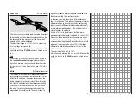
Typical throttle curves for different flight phases:
+100%
+100%
+100%
0%
0%
0%
Output
Output
Output
2
3
4
5
1
2
3
4
5
1
2
3
4
5
1
Control travel
Control travel
Control travel
Hover
Aerobatics
3D
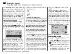
Notes on using the “Throttle limit” function:
We strongly recommend that you make use of the
•
throttle limit function (“
Transmitter control settings
”
menu, page 99). When you use this function the throt-
tle servo is completely disconnected from the throt-
tle / collective pitch stick when the proportional throt-
tle limit control is at its left-hand end-point; the motor
runs at idle and only responds to the Ch 1 trim. This
feature enables you to start the motor from within any
flight phase.
Once the motor is running, turn the throttle limiter
slowly to the opposite end-point, so that full control
of the throttle servo is returned to the throttle / collec-
tive pitch stick. It is important that the throttle limiter
should not restrict the throttle servo at its upper end-
point; you can avoid this by setting the control travel
to +125% in the “Lim” line of the “
Transmitter control
settings
” menu.
Since electric motors by their nature require no idle
•
setting, the only important point when setting up an
electric-powered model helicopter is that the adjust-
ment range of the throttle limiter should be set signifi-
cantly higher and lower than the adjustment range of
the speed controller, which is usually from -100% to
+100%. It may therefore be necessary to set the “Trav-
el” value of the throttle limiter to an appropriate point
in the “Lim” line of the “
Transmitter control settings
”
menu. However, the throttle curve itself has to be fine-
tuned with the helicopter in flight, just like a glow-pow-
ered machine.
Releasing the full throttle range, and imposing the
•
throttle limiter again, trips the switching threshold of
the control switch “C3” (i. e. in either direction); this
switch can be used for automatically starting and
stopping the stopwatch to record the flight time, or
some similar purpose; see page 57.
When you select auto-rotation, the mixer automati-
cally switches the value to a variable pre-set value;
see the section starting on page 124.
Helicopter with speed GOVERNOR (REGULATOR)
In contrast to speed
controllers
, which simply adjust pow-
er output in the same way as a carburettor, speed
gover-
nors
maintain a constant rotational speed in the system
which they regulate; they accomplish this by adjusting the
power output as required. In the case of a glow-powered
helicopter the governor automatically controls the throttle
servo; in an electric-powered machine the governor does
the same with the speed controller.
For this reason speed
governors do not require a classic throttle curve; they
just need a pre-set rotational speed.
Once this is set, the
system rotational speed does not alter unless the system
calls for more power from the motor than is available.
In most cases a speed
governor
is connected to receiver
output 8; see the receiver socket sequence on page 65. If
this socket is already in use, then the throttle limiter func-
tion is not used, since this only affects output 6 - which is
now not occupied - via the “Ch 1
throttle” mixer.
However, if you wish to be able to exploit the conven-
ience and safety features of the throttle limiter, the speed
governor should be connected to receiver output 6 - in
contrast to the usual socket sequence - and the throttle
curve adjusted so that it can simply assume the role of
the “usual” transmitter control.
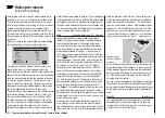
In this case the “throttle curve” only determines the
nominal rotational speed of the speed controller, and this
nominal value is required to remain constant over the full
range of collective pitch; for this reason a horizontal line
should be set in the “Ch 1
throttle” mixer, i. e. every
(collective pitch) input value results in the same (“throt-
tle”) output value. The “height” of the line in the graph
determines the nominal system rotational speed.
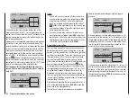
Initially, then, reference point “3” should be erased, and
reference points “1” (input = 0%) and “5” (input = +100%)
set to the same value; for example:
input
output
point
1
0%
+65%
+65%
ch1
normal
thro
The value to be set varies according to the speed gov-
ernor you are using, and also to the desired nominal
rotational speed; you may wish to vary it, of course, in the
various flight phases.
When you select auto-rotation, the mixer automati-
cally switches the value to a variable pre-set value;
see the section starting on page 124.
Summary of Contents for mx-12 Hott
Page 1: ...Programming Manual 33116 mx 16 HoTT 3 en mx 16...
Page 35: ...35 For your notes...
Page 49: ...49 For your notes...
Page 55: ...55 For your notes...
Page 59: ...59 For your notes...
Page 63: ...63 For your notes...
Page 69: ...69 For your notes...
Page 91: ...91 For your notes...
Page 101: ...101 For your notes...
Page 123: ...123 For your notes...
Page 181: ...181 For your notes...
Page 193: ...193 For your notes...


