146
Program description: Telemetry menu
ALL MAX (Servo travel on the “+” side)
In this line you can set the maximum servo travel for the
servo test on the plus side of control travel.
2000 μs corresponds to full travel, 1500 μs corresponds
to the neutral position.
Ensure that the servos do not strike their mechanical
end-stops during the test routine.
ALL MIN (Servo travel on the “-” side)
In this line you can set the maximum servo travel for the
servo test on the minus side of control travel.
1000 μs corresponds to full travel, 1500 μs corresponds
to the neutral position.
Note:
Ensure that the servos do not strike their mechanical
end-stops during the test routine.
TEST
In this line you can start and stop the receiver’s integral
servo test.
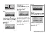
Touch the central
SET
button of the right-hand touch-key
to activate the input field:
RX SERVO TEST
ALL–MIN : 1000µsec
ALL–MAX : 2000µsec
ALARM VOLT : 3.8V
ALARM TEMP–:–10°C
ALARM TEMP+: 55°C
CH OUTPUT TYPE:ONCE
TEST :
STOP
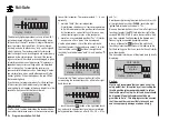
Now select
START
with one of the arrow buttons of the
right-hand touch-key:
RX SERVO TEST
ALL–MIN : 1000µsec
ALL–MAX : 2000µsec
ALARM VOLT : 3.8V
ALARM TEMP–:–10°C
ALARM TEMP+: 55°C
CH OUTPUT TYPE:ONCE
TEST :
START
Touch the central
SET
button of the right-hand touch-
key to start the test-run. The input field now reverts from
highlighted to “normal”:
RX SERVO TEST
ALL–MIN : 1000µsec
ALL–MAX : 2000µsec
ALARM VOLT : 3.8V
ALARM TEMP–:–10°C
ALARM TEMP+: 55°C
CH OUTPUT TYPE:ONCE
TEST : START
To stop the servo test, re-activate the input field as de-
scribed previously, then select
STOP
and confirm your
choice with the
SET
button of the right-hand touch-key.
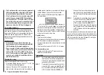
ALARM VOLT (low receiver voltage warning)
ALARM VOLT monitors the receiver voltage. The thresh-
old can be set to any value within the range 3.0 to 6.0
Volt. If the voltage falls below the set alarm limit, an
audible signal (interval beeping, long / short) is trig-
gered, and “
VOLT.E
” flashes at top right in all “
RX …
”
screen displays:
RX SERVO
REVERSE : OFF
CENTER : 1500µsec
TRIM : –000µsec
TRAVEL– : 150%
OUTPUT CH: 01
: 150%
PERIOD : 20msec
VOLT.E
The parameter “
R-VOLT
“ is also highlighted in the “
RX
DATAVIEW
” display:
S–STR100% R–TEM.+28°C
L PACK TIME 00010msec
L.R-VOLT:03.5V
S–QUA100%S–dBM–030dBM
SENSOR1 :00.0V 00°C
SENSOR2 :00.0V 00°C
R-VOLT :
03.7
V
RX DATAVIEW
VOLT.E
ALARM TEMP +/- (receiver temperature monitor)
These two options monitor the temperature of the
receiver: a lower limit value “ALARM TEMP-” (-20 ...
+10°C) and an upper limit value “ALARM TEMP+” (50 ...
80°C) can be programmed. If the temperature exceeds
the upper limit or falls below the lower one, an audible
signal (continuous beeping) is triggered, and “
TEMP.E
”
appears at top right in all receiver displays. The param-
eter “
R-TEM
“ is also highlighted in the “
RX DATAVIEW
”
display.
Ensure that the receiver remains within the permitted
temperature range under all flight conditions (ideally
between -10 and +50°C).
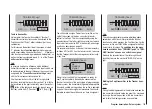
CH OUTPUT TYPE
At this point you can select how the receiver outputs are
to be addressed.
ONCE
•
RX SERVO TEST
ALL–MIN : 1000µsec
ALL–MAX : 2000µsec
ALARM VOLT : 3.8V
ALARM TEMP–:–10°C
ALARM TEMP+: 55°C
TEST : START
CH OUT TYPE:
ONCE
Summary of Contents for mx-12 Hott
Page 1: ...Programming Manual 33116 mx 16 HoTT 3 en mx 16...
Page 35: ...35 For your notes...
Page 49: ...49 For your notes...
Page 55: ...55 For your notes...
Page 59: ...59 For your notes...
Page 63: ...63 For your notes...
Page 69: ...69 For your notes...
Page 91: ...91 For your notes...
Page 101: ...101 For your notes...
Page 123: ...123 For your notes...
Page 181: ...181 For your notes...
Page 193: ...193 For your notes...


