156
Program description: Trainer system
The Pupil transmitter must always be operated in
•
PPM mode, regardless of the type of RF link be-
tween the Teacher transmitter and the model.
If the Pupil transmitter is connected using a DSC
•
socket, then you should ALWAYS leave the Pu-
pil transmitter’s On / Off switch at the “OFF” posi-
tion, as this is the only way to ensure that the Pu-
pil transmitter module does not generate an RF
signal even when the DSC lead is plugged in.
Trainer mode operations
Connect the two transmitters using the appropriate
lead; see the overview on the next page: connect the
plug marked “
M
” (Master) to the socket on the Teacher
transmitter, and the plug marked “
S
” (Student) (not
present on all leads) to the appropriate socket on the
Pupil transmitter.
Important notes:
It is essential to check that all functions are
•
transferred correctly to the prepared model BE-
FORE initiating Trainer mode operations.
If you are using a Trainer lead with three-pole bar-
•
rel connectors, on no account connect one of the
ends marked “S” or “M” to a DSC system sock-
et, as it is not suitable for this purpose. The DSC
socket is only suitable for leads fitted with two-
pole barrel connectors.
Checking the system
Operate the assigned Trainer transfer switch:
If the screen display changes from „
•
T“ to „
P“, the
Trainer system is working properly.
However, if the central LED flashes blue / red at a
•
high rate, and at the same time the transmitter emits
audible signals, then there is a problem with the con-
nection between Pupil and Teacher transmitter.
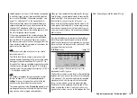
At the same time the following warning appears in
the base display …
no
student
signal
… and in the “
Trainer
” menu the display changes to
“-P” on the left. If this should happen, note that all the
functions automatically remain under the control of
the Teacher transmitter, regardless of the position of
the Trainer transfer switch; this ensures that the mod-
el is not out of control at any time.
Possible errors:
Pupil transmitter not ready
•
The interface in the Pupil transmitter, which replaces
•
the RF module, is not connected correctly
Incorrect cable connection: see next section for cable
•
selection
Pupil transmitter not set to PPM (10, 18, 24) mode.
•
Further possible errors:
Teacher transmitter and HoTT receiver in trainer
•
model not correctly “bound”.
Trainer leads
4179.1
For Trainer mode operations between any
two
Graupner
transmitters equipped with a
DSC socket - identifiable by two-pole barrel
connectors at both ends.
3290.7
Trainer lead for connecting a Teacher trans-
mitter with DSC socket (e. g.
mx-16
HoTT),
or a transmitter retro-fitted with the option-
al DSC module, Order No.
3290.24
, to a
Graupner
Pupil transmitter with opto-elec-
tronic Pupil socket - identifiable by the letter
“
S
” at the end with the three-pole barrel con-
nector.
3290.8
Trainer lead for connecting a Pupil transmit-
ter with DSC socket (e. g.
mx-16
HoTT)
or a transmitter retro-fitted with the option-
al DSC module, Order No.
3290.24
, to a
Graupner
Teacher transmitter with opto-elec-
tronic Teacher socket - identifiable by the let-
ter “
M
” at the end with the three-pole barrel
connector.
For more detailed information about the leads and mod-
ules for the Teacher and Pupil transmitters listed on this
page, please refer to the operating instructions supplied
with your transmitter, the main
Graupner
FS catalogue,
or the Internet at www.graupner.de.
Summary of Contents for mx-12 Hott
Page 1: ...Programming Manual 33116 mx 16 HoTT 3 en mx 16...
Page 35: ...35 For your notes...
Page 49: ...49 For your notes...
Page 55: ...55 For your notes...
Page 59: ...59 For your notes...
Page 63: ...63 For your notes...
Page 69: ...69 For your notes...
Page 91: ...91 For your notes...
Page 101: ...101 For your notes...
Page 123: ...123 For your notes...
Page 181: ...181 For your notes...
Page 193: ...193 For your notes...


