FR200 Series Vector control inverter
- 88 -
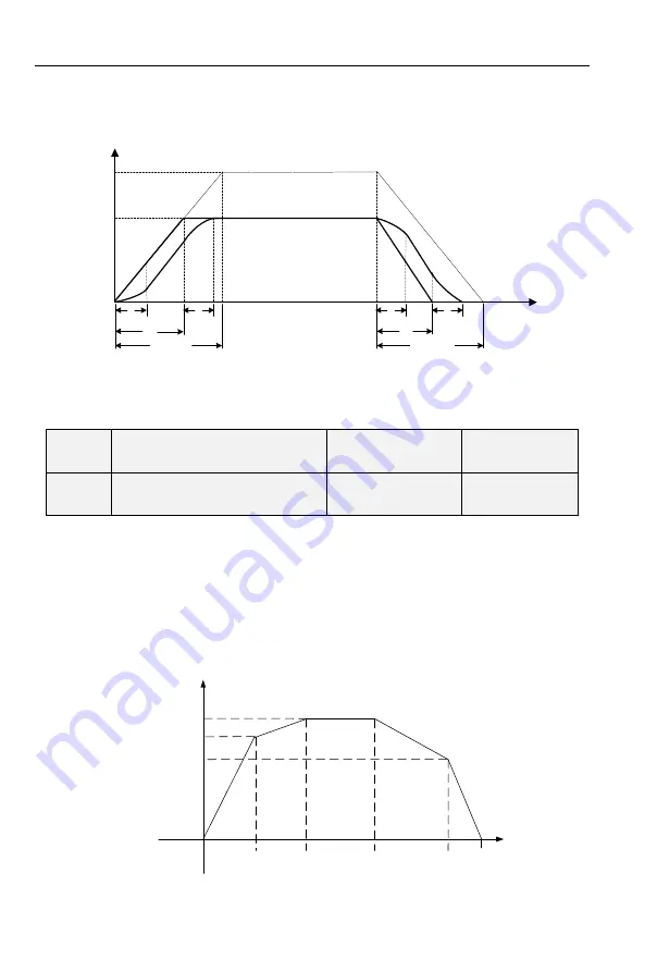
The 1st section and the last section in accelerating or decelerating are in smooth transition. The
acceleration/deceleration curve is similar to S curve. When it is in S curve, the final
acceleration/deceleration time= S curve time+ Linear acceleration/deceleration time. See Figure 6-13
for 2 acceleration/deceleration modes.
See Figure 6-6 for 2 acceleration/deceleration modes.
0
Output frequency(Hz)
T
Fmax
Fset
①
①
①
①
Setting acceleration
time
Setting deceleration
time
②
③
①
S section curve time
②
Time required for linear acceleration time
③
Time required for linear deceleration time
Figure 6-6
F03.13
Frequency switchover point
between acceleration time 1 and
acceleration time 2
Range:0.00
~
Fmax
Default:0.00Hz
F03.14
Frequency switchover point
between deceleration time 1 and
deceleration time 2
Range:0.00
~
Fmax
Default:0.00Hz
This function is valid when motor 1 is selected and acceleration/deceleration time switchover is
not performed by means of DI terminal. It is used to select different groups of acceleration/deceleration
time based on the running frequency range rather than DI terminal during the running process of the
AC drive.
During acceleration, if the running frequency is smaller than the value of F03.13, acceleration time
2 is selected. If the running frequency is larger than the value of F03.13, acceleration time 1 is
selected.
During deceleration, if the running frequency is larger than the value of F03.14, deceleration time
1 is selected. If the running frequency is smaller than the value of F03.14, deceleration time 2 is
selected.
Figure 6-7 Acceleration/deceleration time switchovers.
Output frequency(Hz)
Set frequency
F03.13
F03.14
Acceleration
time
2
Time
Acceleration
time 1
Deceleration
time
1
Deceleration
time
2
Figure 6-7


