FR200 Series Vector control inverter
- 115 -
F12.09
Reference 9
Range:-100.0
~
100.0%
Default:0.0%
F12.10
Reference 10
Range:-100.0
~
100.0%
Default:0.0%
F12.11
Reference 11
Range:-100.0
~
100.0%
Default:0.0%
F12.12
Reference 12
Range:-100.0
~
100.0%
Default:0.0%
F12.13
Reference 13
Range:-100.0
~
100.0%
Default:0.0%
F12.14
Reference 14
Range:-100.0
~
100.0%
Default:0.0%
F12.15
Reference 15
Range:-100.0
~
100.0%
Default:0.0%
At most 16 steps of multi-feference can be set by different status combinations of
" multi-feference terminals 1
~
4" of digital input.
Multi-reference can be the setting source of frequency, V/F separated voltage and process PID.
The multi-reference is relative value and ranges from -100.0% to 100.0%.
As frequency source, it is a percentage relative to the maximum frequency. As V/F separated
voltage source, it is a percentage relative to the rated motor voltage. As process PID setting source, it
does not require conversion.
Multi-reference can be switched over based on different states of DI terminals. For details, see the
descriptions of group F4.
F12.16
Reference 0 source
Range:0
~
6
Default: 0
0: Digital setting
(
F12.00)
1: keypad potentiometer
2
:
AI1
3: Process PID output
4: X7/HI pulse input
5
:
AI2
6
:
AI3
It determines the setting channel of reference 0. You can perform convenient switchover between
the setting channels. When multi-reference or simple PLC is used as frequency source, the switchover
between two frequency sources can be realized easily.
F12.17
Running mode of simple PLC
Range:0000
~
1113
Default:000
Unit's place: PLC running mode
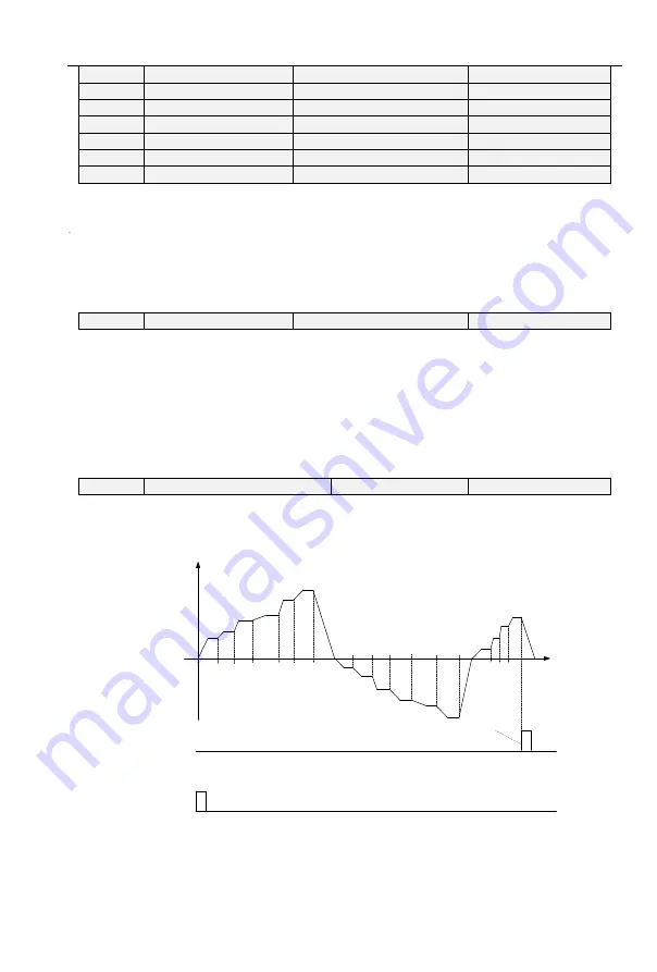
0: Stop after a single cycle
PLC stops upon the completion of one c
ycle and it won’t be started unless another run command
is given, shown as Fig. 6-22.
0
f0
a0
T0
a1
f1
f2
f3
f4
f5
f6
f7
f8
f9
f10
f11
f12
f13
f14
f15
a2
a3
a4
a5
d6
a6
a7
a8
a9
a10
a11
d12
a12
a13
a14
a15
T1
T2
T3
T4
T5
T6
T7
T8
T9
T10
T11
T12
T13T14 T15
d15
Run command
PLC cycle completed
Pulse length:250ms
Output frequency(Hz)
Fig. 6-23
1: Continue to run with the last frequency after a single cycle
After the completion of one cycle, PLC maintains the running frequency and direction of the last
step. See the figure below:


